Power supply control device

Inactive Publication Date: 2012-03-01
PANASONIC CORP
View PDF38 Cites 12 Cited by
  • Summary
  • Abstract
  • Description
  • Claims
  • Application Information

AI Technical Summary

Benefits of technology

[0018]In the power supply control device, the tension preventing member may include a tubular member whose inner diameter is decreased by being held by the cap member to prevent the corresponding cable from being tensioned. Besides, the body part and the tensile prevention member may be provided with depression-projection engaging parts that are engaged with each other in a circumferential direction of each cable to preven

Problems solved by technology

Herein, if an electric leakage occurs on the vehicle side when the battery is charged, an excessive current may flow into the in-vehicle ch

Method used


Image

  • Power supply control device
  • Power supply control device
  • Power supply control device

Examples


Embodiment Construction

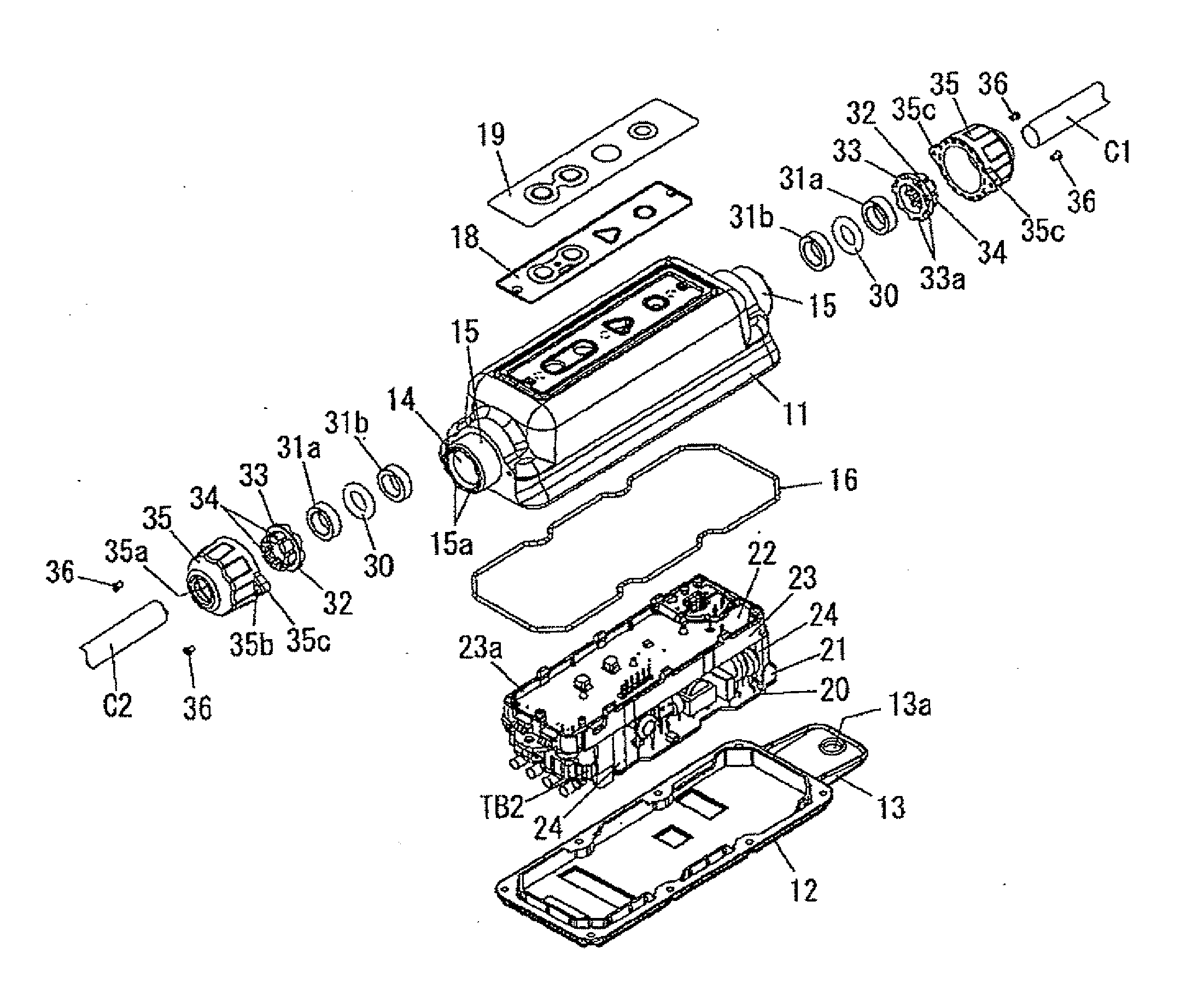
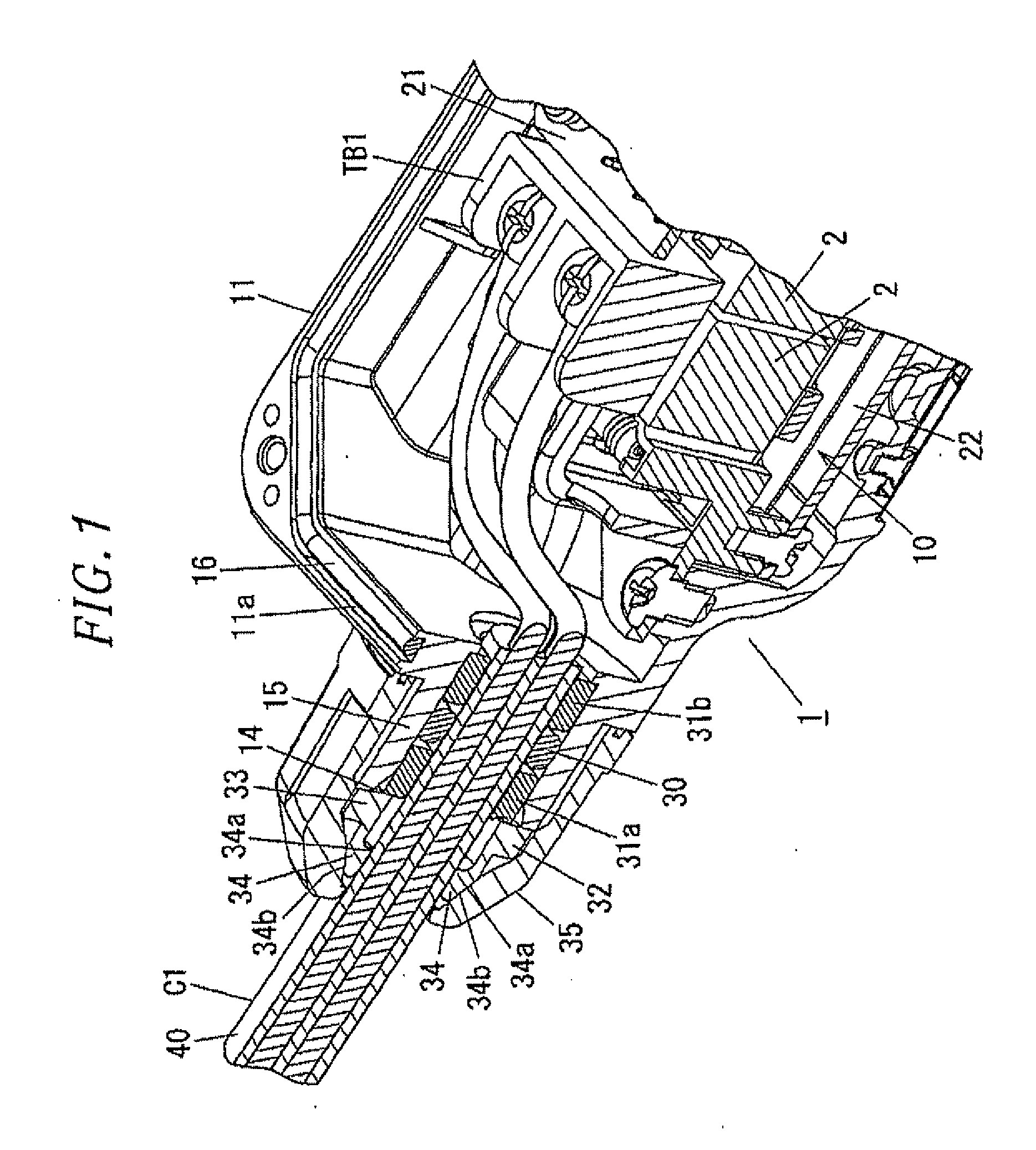
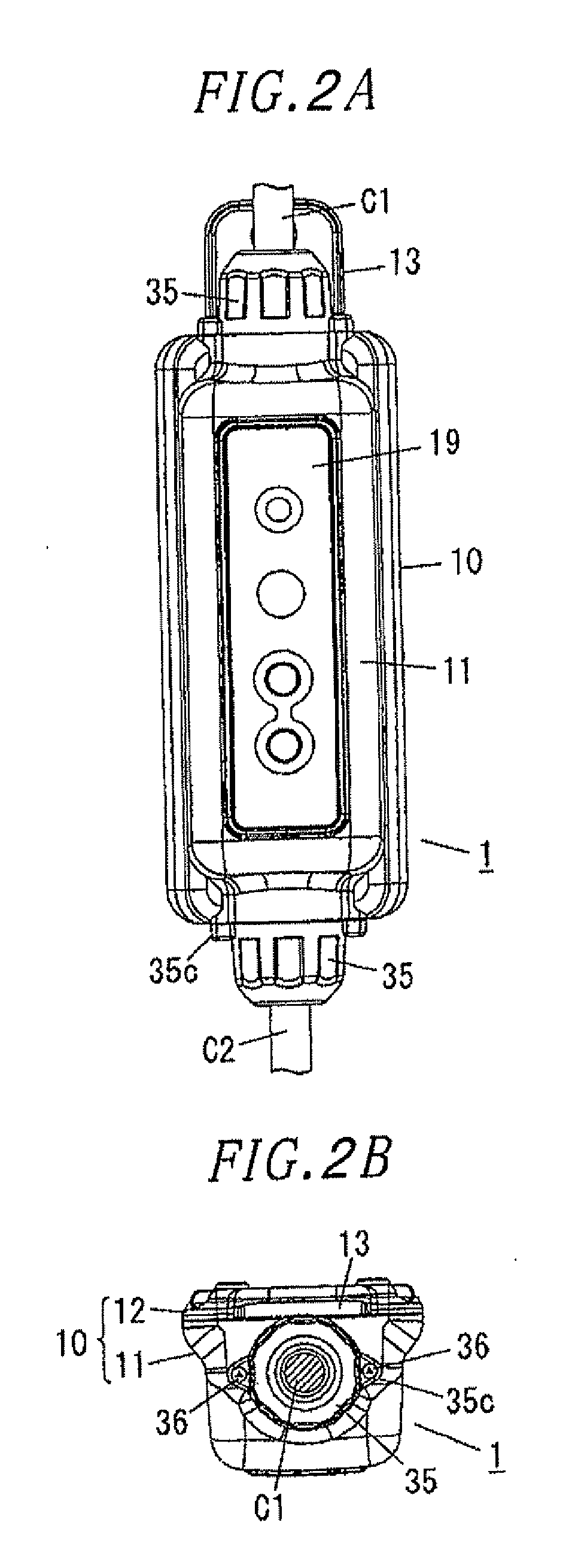
[0034]Hereinafter, an embodiment of a power supply control device in accordance with the present invention will be described with reference to the drawings. The power supply control device of the present embodiment is used for charging an electric vehicle (an electric vehicle of storage battery type, a plug-in hybrid car, and the like) at home, and is adapted to turn on and off power supply to a charging circuit provided in the electric vehicle. Hereinafter, up-down and left-right directions are defined based on the directions shown in FIG. 2A, and a front-rear direction is defined based on the right-left direction in FIG. 2D. However, the above directions are defined for convenience of explanation, and do not necessarily congruous with the directions in the actual use state of the power supply control device.

[0035]The power supply control device 1 includes a housing (body part) 10 having a body 11 with a rectangular parallelepiped shape of which one side is opened; and a cover 12 a...


PUM


Abstract

A power supply control device includes a body part in which a circuit block is accommodated; a first cable drawn outside from the body part to be connected to a charge circuit of an electric vehicle; a second cable drawn outside from the body part to be connected to a power source; and a sealing member sealing a gap between each of the cables and a corresponding cable passing port of the body part. The power supply control device further includes an outer restriction member provided at each of the cables on an outer side than the sealing member to prevent the corresponding cable from being bent.

Description

FIELD OF THE INVENTION[0001]The invention relates to a power supply control device.BACKGROUND OF THE INVENTION[0002]In recent years, an electric vehicle driven by electric power, such as an electric vehicle (EV) with a storage battery and a plug-in hybrid vehicle (PHV), has been practically used. Such electric vehicle has an in-vehicle charger that receives electric power from an external power source, such as a commercial 100 Vac power source, to charge a built-in battery for traveling. Herein, if an electric leakage occurs on the vehicle side when the battery is charged, an excessive current may flow into the in-vehicle charger. Therefore, a power supply control device is used for intercepting the power supply to the electric vehicle when the leakage occurs (e.g., see Japanese Patent Application Laid-open No. 2009-240053).[0003]FIG. 11 is a block circuit diagram of a power supply control device 101. The power supply control device 101 is configured to accommodate a relay 2, a zero...

Claims


Application Information

Patent Timeline
IPC IPC(8): H02G15/10
CPCB60L3/0069B60L11/1816B60L2230/12B60L2230/16H02G15/007H02G15/013Y02T10/7005Y02T90/121Y02T90/128Y02T90/14Y02T90/163Y02T10/7088H02G15/113B60L53/18B60L53/305Y02T10/7072Y02T90/12Y02T90/16Y02T10/70
Inventor MIHARA, HARUHIKONAKAMURA, SHINICHIINAGAKI, NOBORU
Owner PANASONIC CORP
Why Eureka
Try Eureka