Auger with Butterfly Flighting

a technology of augers and butterflies, applied in the field of augers for drilling holes, can solve the problems of serious accidents and even deaths of augers with continuous flying, and achieve the effect of less susceptible to accidents

Inactive Publication Date: 2012-03-01
KING KUTTER
View PDF4 Cites 6 Cited by
  • Summary
  • Abstract
  • Description
  • Claims
  • Application Information

AI Technical Summary

Benefits of technology

[0005]An auger according to the present disclosure does not have continuous helical flighting on the auger shaft. The cutting head of the auger comprises a generally flat blade disc with a plurality of cutting blades affixed to the disc. An auger tip extends below the disc. A generally butterfly-shaped flighting extends from the auger shaft and is positioned above the cutting head, but does not extend continuously along the auger shaft. In operation of the auger, a column of soil accumulates on a top surface of the flat blade disc for removal from the hole. The flighting “lightens” the column of soil that accumulates to enable a higher column to accumulate on the flat blade disc. Because the flighting is relatively small (in relation to continuous-flighting augers) and is usually below the ground during post hole digging operations, the auger may be less susceptible to accidents caused by flighting on the rotating shaft.
[0006]For purposes of summarizing the invention, certain aspects, advantages, and novel features of the invention have been described herein. It is to be understood that not necessarily all such advantages may be achieved in accordance with any one particular embodiment of the invention. Thus, the invention may be embodied or carried out in a manner that achieves or optimizes one advantage or group of advantages as taught herein without necessarily achieving other advantages as may be taught or suggested herein.

Problems solved by technology

However, continuous-flighting auger-based post hole diggers have been the cause of serious accidents and even fatalities due to the flighting on the rotating auger shaft catching clothing, hair, or body parts of individuals who may be in the digging area.

Method used


Image

  • Auger with Butterfly Flighting
  • Auger with Butterfly Flighting
  • Auger with Butterfly Flighting

Examples


Embodiment Construction

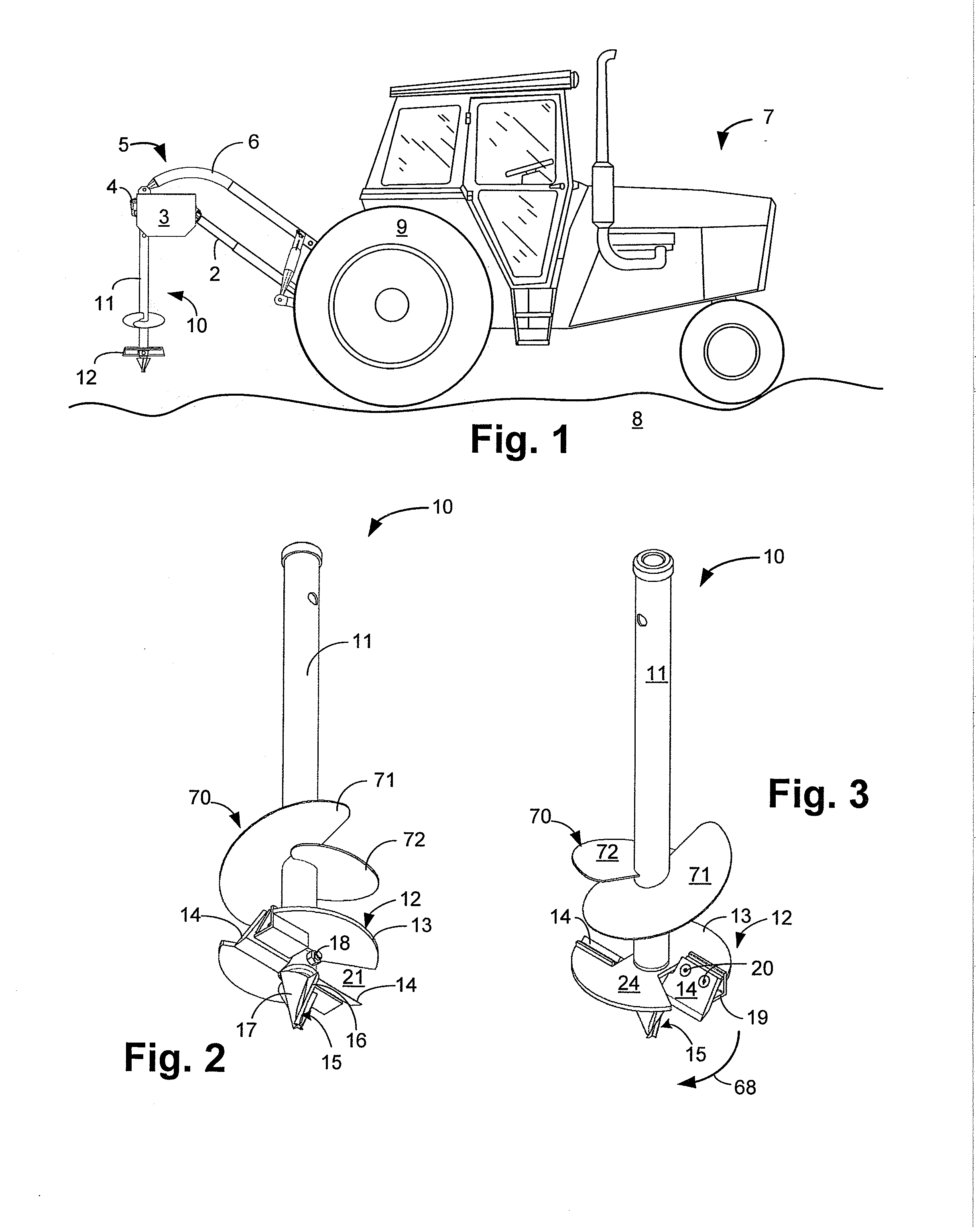
[0030]FIG. 1 is a side plan view of a post hole digger 5 according to an exemplary embodiment of the present disclosure. The digger 5 is shown installed on a tractor 7 and is used to dig generally-cylindrical holes (not shown) in the ground 8, for example, holes for fence posts. The digger 5 is disposed at the rear of the tractor 7 between the rear wheels 9 (only one of which is illustrated).

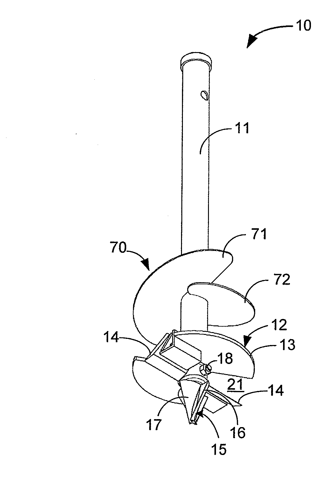
[0031]The digger 5 comprises an auger 10 for drilling into the ground 8. The auger 10 is supported by a top support arm 6 that extends from the tractor 7 as further discussed herein. A rotating shaft 2 extends from a PTO shaft (not shown) of the tractor 7 and translates rotation from the PTO shaft to a gearbox 4, and ultimately to the auger 10. A shield 3 covers moving parts (not shown) that can pose a safety hazard to users (not shown) of the digger 5.

[0032]The auger 10 comprises a cutting head 12 rigidly mounted to a rotatable shaft 11. The shaft 11 extends downwardly from the gearbox 4, which...


PUM


Abstract

An auger for digging holes in soil is coupled to a gearbox and powered by the power take-off of a tractor. The auger comprises a shaft with a cutting head disposed near its bottom end. The cutting head comprises a plurality of cutting (i.e. digging) blades that cut into soil. Flighting disposed above the cutting head moves and lightens soil, but the flighting does not extend far above the cutting head. The majority of the shaft is free from protrusions that may ensnare a user of the auger during use.

Description

CROSS-REFERENCE TO RELATED APPLICATIONS[0001]This application claims the benefit of U.S. Provisional Application No. 61 / 379,223 titled “Auger with Butterfly Flighting,” filed on Sep. 1, 2010, the entire contents of which are herein incorporated by reference. This application further claims the benefit of U.S. Provisional Application No. 61 / 507,146 titled “Post Hole Digger,” filed on Jul. 13, 2011, the entire contents of which are herein incorporated by reference.FIELD OF THE INVENTION[0002]The present invention relates generally to the field of digging devices, and more particularly relates to an auger for drilling holes.BACKGROUND AND SUMMARY OF THE INVENTION[0003]A post hole auger for drilling holes in soil is provided. In one embodiment, the auger is powered by a power take-off (PTO) of a tractor.[0004]Prior art tractor-based post hole augers are generally continuous-flighting augers. “Flighting” refers to the helical blade extending from the rotating shaft of traditional flighte...

Claims


Application Information

Patent Timeline
Patent Type & Authority Applications(United States)
IPC IPC(8): E21B10/44
CPCE21B7/027
Inventor FRALEY, J. PHILLIPDAVIS, III, JOHN W.
Owner KING KUTTER
Why Eureka
Try Eureka