Formwork support system and construction method

A support system and formwork technology, applied in the direction of formwork/formwork/work frame, connection parts of formwork/formwork/work frame, formwork/formwork member, etc., can solve the problems of difficult pouring and difficult material turnover, etc. Achieve high construction efficiency, avoid material turnover difficulties, and stabilize the system.

Active Publication Date: 2022-01-14
CHINA GEZHOUBA GRP MECHANICAL & ELECTRICAL CONSTR +1
View PDF5 Cites 3 Cited by
  • Summary
  • Abstract
  • Description
  • Claims
  • Application Information

AI Technical Summary

Problems solved by technology

[0003] The technical problem to be solved by the present invention is to provide a formwork support system and a construction method. Compared with the traditional method, the construction method has a stable structure and high construction efficiency, and can effectively avoid the problems of difficult material turnover and difficult pouring. The formwork support system is stable, safe and less prone to accidents

Method used


Image

  • Formwork support system and construction method
  • Formwork support system and construction method
  • Formwork support system and construction method

Examples


Embodiment 1

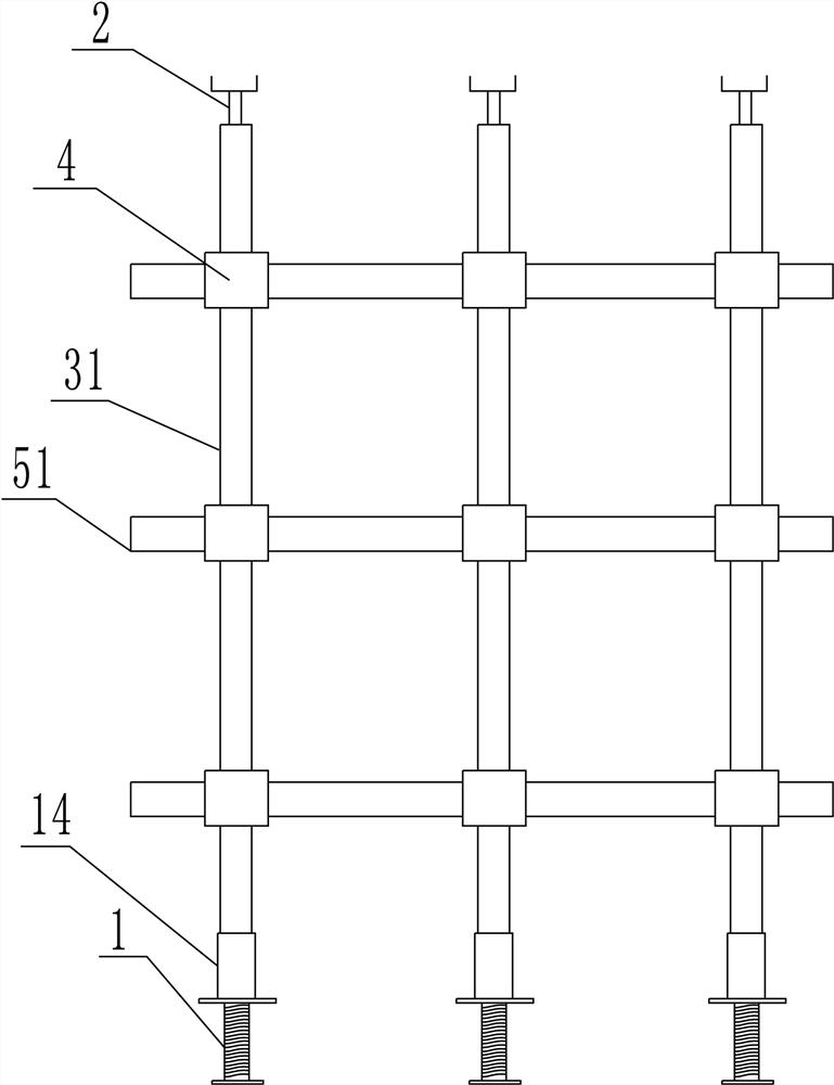
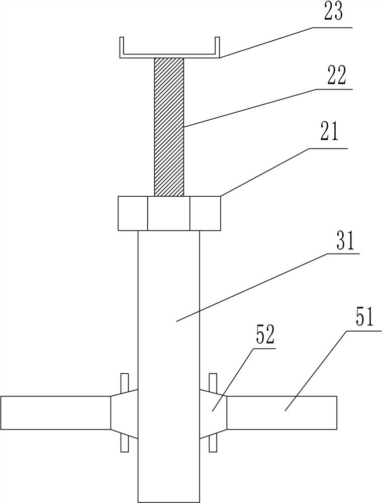
[0037] Such as Figure 1~Figure 7 Among them, a formwork support system, including a support system and a formwork system; the support system includes an adjustable base 1, the bottom end of the adjustable base 1 is connected to the positioning point, and the top end of the adjustable base 1 is socketed with the vertical rod 31 system; the vertical rod 31 The system is connected with a cross bar 51 system through the buckle node 4; the scissor brace or inclined bar is connected between the vertical bar 31 system and the cross bar 51 system; Adjust the bracket 232 to cooperate, and the wall template is bolted to the support system.

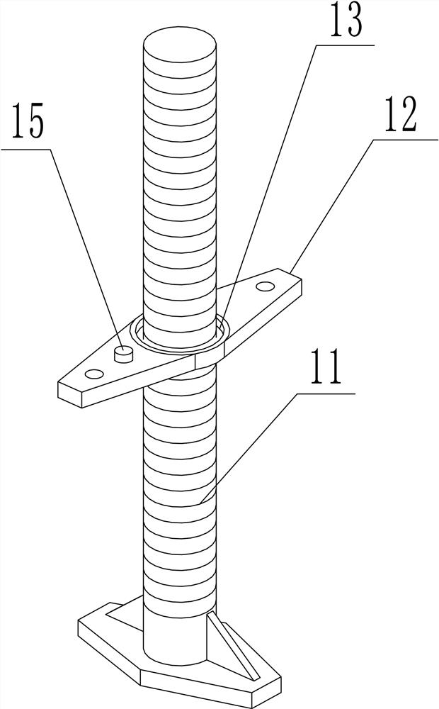
[0038] Preferably, the adjustable base 1 includes a threaded rod 11, the surface of the threaded rod 11 is threadedly connected with a support plate 12, the upper surface of the support plate 12 is provided with an annular positioning groove 13; the bottom surface of the positioning groove 13 is provided with a sheet pressure sensor, the pressure s...

Embodiment 2

[0058] (1) Roof formwork structure:

[0059] The roof template is made of 15mm film-coated wood plywood, the main keel is made of 6.3# channel steel, the secondary keel is made of 40×80mm wooden beams, and the distance between the back corrugated is 150mm. When the formwork is installed, ensure that there is a keel under the joint, and the joint is tight, and there is no wrong platform on the surface.

[0060] (2) Support system:

[0061] See the floor formwork parameter table for the distance between vertical and horizontal poles 31 of buckle-type steel pipe frame on the slab chassis. The upper part of the pole 31 is provided with a jacking bracket. The gap with the inner diameter of the column steel pipe shall not be greater than 3mm, and the upper and lower concentricity shall be ensured during installation.

[0062] The erection height of each floor of the main factory building shall not exceed 8m, and shall be arranged in the following way: vertical slanting rods shall ...


PUM


Abstract

The invention discloses a formwork support system and a construction method. The formwork support system comprises a support system and a formwork system. The support system comprises an adjustable base, wherein the bottom end of the adjustable base is connected with a positioning point, and the top end of the adjustable base is sleeved with vertical rod systems. A transverse rod system is connected between the vertical rod systems through disc buckle joints; a cross bridging or an inclined rod is connected between the vertical rod system and the transverse rod system. The formwork system comprises a top formwork and a wall formwork, wherein the top formwork is matched with an adjustable bracket at the top of the support system, and the wall formwork is connected with the support system through bolts. Compared with a traditional method, the construction method is stable in structure, high in construction efficiency and capable of effectively avoiding the problems that materials are difficult to transfer and pouring is difficult, the whole formwork support system is stable and safe, and accidents are not prone to happening.

Description

technical field [0001] The invention belongs to the technical field of construction of underground powerhouses of hydraulic structures, and in particular relates to a formwork support system and a construction method. Background technique [0002] The main engine room floor (turbine floor, bus bar floor, generator floor) of the underground powerhouse is designed with a thick slab structure, the upstream and downstream are made of concrete side walls, and the middle floors are respectively equipped with unit support structures such as volutes, machine piers, and windshields. In the process of building construction, due to the high safety factor of the underground workshop and the difficulty in material turnover, the reliability of the formwork reinforcement and the stability of the beam support system are engineering control difficulties; therefore, it is necessary to design a formwork support system and construction method to solve the above problems . Contents of the inve...

Claims


Application Information

Patent Timeline
Patent Type & Authority Applications(China)
IPC IPC(8): E04G9/02E04G11/06E04G17/00E04G21/00G01L5/00G08B5/36G08B21/24
CPCE04G9/02E04G11/06E04G17/00E04G21/00G01L5/0028G08B21/24G08B5/36Y02E10/20
Inventor 卫学深袁峥卫文秀李壮王国刚卫学识段润甜蒋先龙
Owner CHINA GEZHOUBA GRP MECHANICAL & ELECTRICAL CONSTR
Why Eureka
Try Eureka