Axial gap rotating electrical machine

a technology of axial gap and electrical machine, which is applied in the direction of dynamo-electric machines, electrical apparatus, magnetic circuit shapes/forms/construction, etc., can solve the problems of increasing vibration and noise, increasing the mechanical strength of the joints, and increasing the number of assembly parts, so as to reduce the number of man-hours in assembling a motor, the effect of simplifying the manufacturing process of the motor

Active Publication Date: 2012-03-01
HITACHI METALS LTD
View PDF7 Cites 3 Cited by
  • Summary
  • Abstract
  • Description
  • Claims
  • Application Information

AI Technical Summary

Benefits of technology

[0024]The structure of the axial gap rotating electrical machine of the invention makes it possible to significantly reduce the number of assembly parts and significantly reduce the number of man-hours in assembling a motor. As a result, it is possible to simplify the manufacturing process for the motor and shorten the manufacturing time therefor. The manufacturing cost of the motor can be reduced. At the same time, the assembling accuracy can be enhanced and thus the performance of the motor can be enhanced.

Problems solved by technology

If variation is produced in the position or disposition of stator cores, the cogging torque of the axial gap rotating electrical machine will become larger than a calculated value and this will increase vibration and noise.
However, the structure disclosed in Patent Document 3 (JP-A-2008-35599) involves a problem associated with joining between the support members and the stator cores.
The resin-molded stator reduces the mechanical strength of the joints.
As the rotating electrical machine rotates, the joints are influenced by vibration and there is a possibility that a stator core is displaced.
In high-speed rotation, especially, a problem of strength is prone to rise.
To sum up, the rotating electrical machine structures in the above patent documents involve problems associated with the accurate positioning of stator cores in the assembly of rotating electrical machines and the simplification of a manufacturing process.
As a result, these technologies cannot contribute to the enhancement of the performance of rotating electrical machines as finished products.

Method used


Image

  • Axial gap rotating electrical machine
  • Axial gap rotating electrical machine
  • Axial gap rotating electrical machine

Examples


embodiments

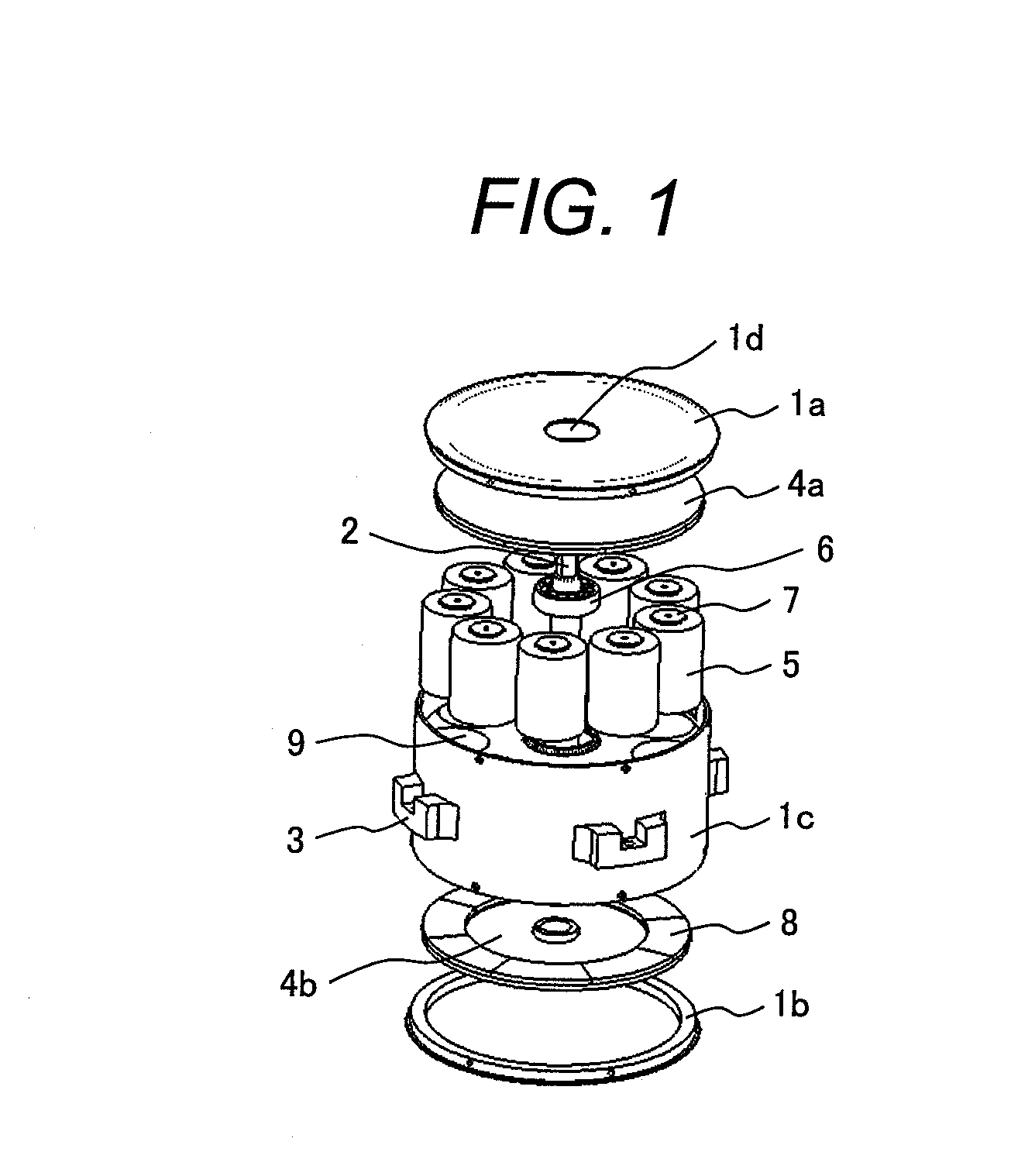
[0046]FIG. 2 illustrates the appearance and shape of an ordinary axial gap rotating electrical machine, which includes a shaft 2 extended upward in the center of a substantially cylindrical rotating electrical machine case 1 formed of nonmagnetic material . The shaft 2 maybe taken out of the rotating electrical machine case 1 on both sides; however, it is taken out only on one side in this example.

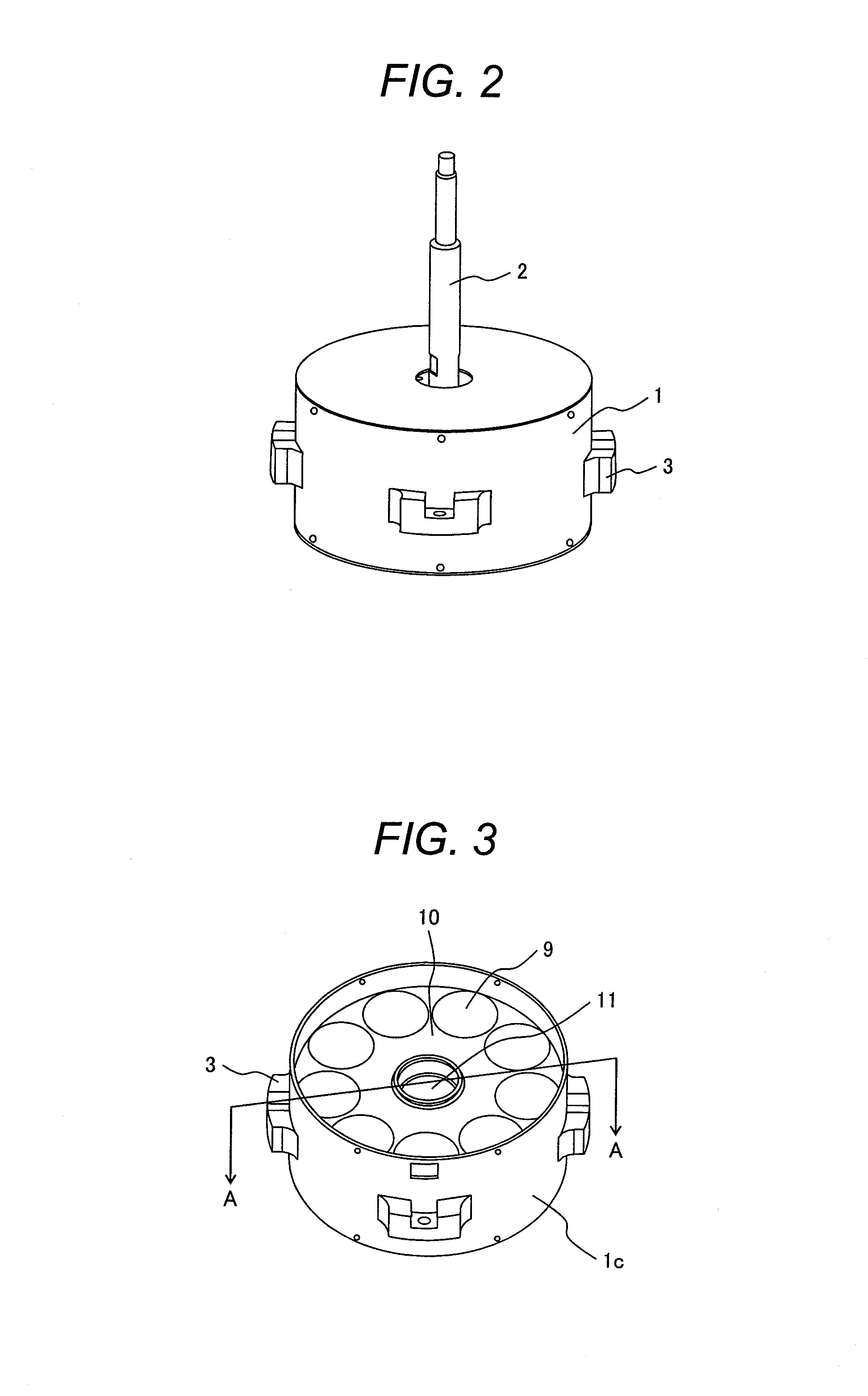
[0047]The rotating electrical machine case 1 is provided with attaching portions 3 for installing the rotating electrical machine. When the invention is applied to a motor, it is desirable that a nonmagnetic and nonconductive material, such as resin and ceramic, should be used for the case 1 for the prevention of production of eddy current loss. There is no limitation on the material of the attaching portions.

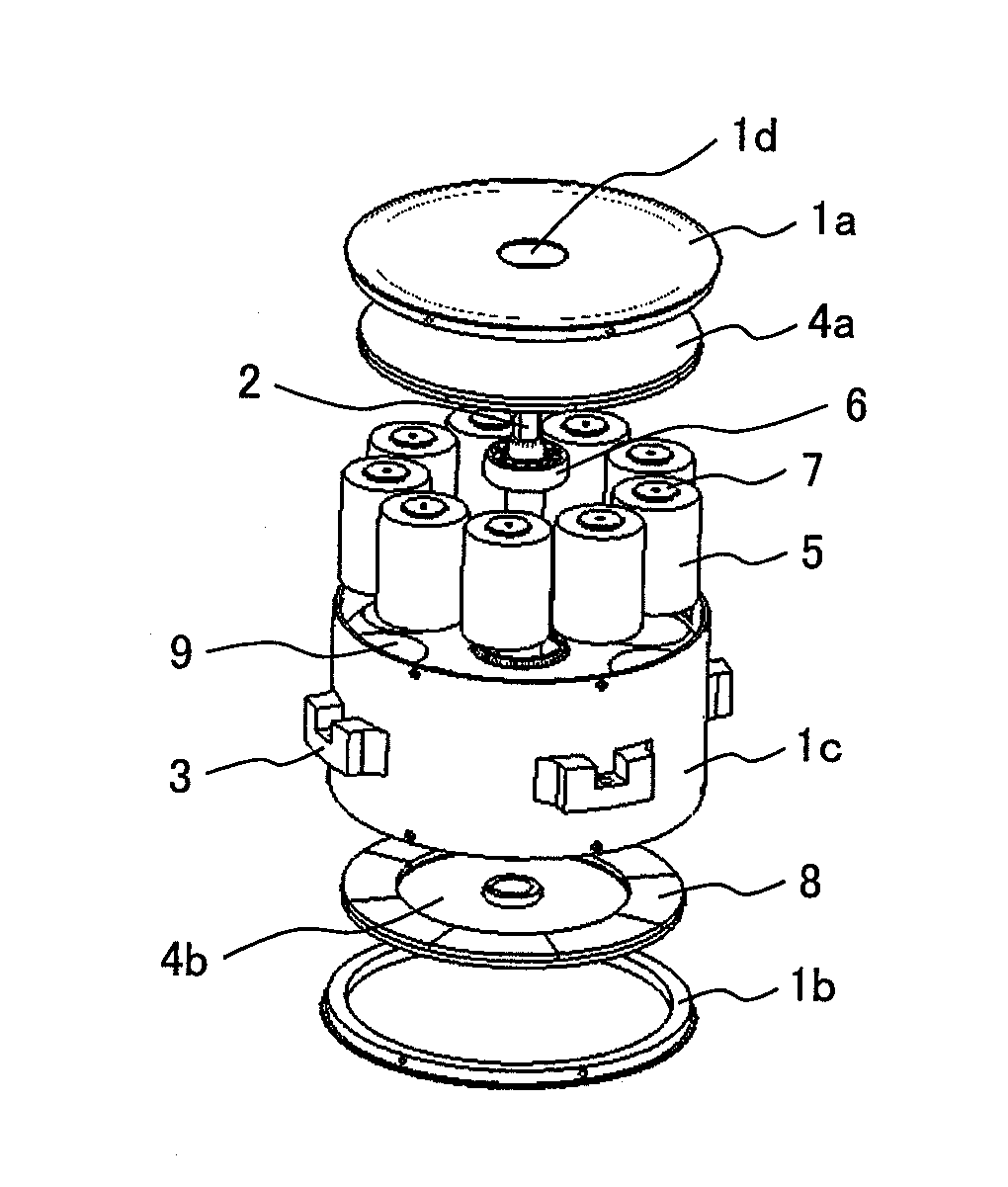
[0048]FIG. 1 is a development illustrating the arrangement of devices housed in the rotating electrical machine case 1. The rotating electrical machine case 1 is comprised of an upper...


PUM


Abstract

When an axial gap rotating electrical machine is assembled, stator cores are accurately positioned and a manufacturing process therefor is simplified. The axial gap rotating electrical machine is comprised of: a housing frame body having a first space in the cylindrical central part thereof and multiple second spaces located in the circumferential direction which have the same distances from the center; a shaft rotatably provided in the first space in the housing frame body; a core placed in each of the second spaces in the housing frame body and a coil arranged outside of the core; a rotor yoke fixed on the shaft, extended in the direction of the circumference thereof, and having multiple magnets arranged in circumferential positions confront the cores; and a case having a hole for the shaft and housing the housing frame body and the rotor yoke.

Description

CLAIM OF PRIORITY[0001]The present application claims priority from Japanese Patent application serial no. 2010-190343, filed on Aug. 27, 2010, the content of which is hereby incorporatedby reference into this application.FIELD OF THE INVENTION[0002]The present invention relates to an axial gap rotating electrical machine.BACKGROUND OF THE INVENTION[0003]In general, axial gap rotating electrical machines are comprised of : a pair of rotor having two circular disks provided on the respective opposite surfaces thereof with permanent magnets and a shaft coupling the circular disks together, located in the centers thereof; a stator made up of multiple cores and coils to which the permanent magnets are opposed with a gap in between; and a pair of bearings rotatably supporting both ends of the shaft and bearing holders holding them.[0004]As an example of axial gap rotating electrical machines in which a rotor and a stator are arranged opposite to each other in the direction of the central...

Claims


Application Information

Patent Timeline
Patent Type & Authority Applications(United States)
IPC IPC(8): H02K21/24
CPCH02K1/14H02K21/24H02K1/182
Inventor WANG, ZHUONANENOMOTO, YUJIITO, MOTOYAMASAKI, RYOSOITABASHI, HIROMITSUHUANG, BAIYING
Owner HITACHI METALS LTD
Why Eureka
Try Eureka