Multi-Mode Dimmer Interfacing Including Attach State Control

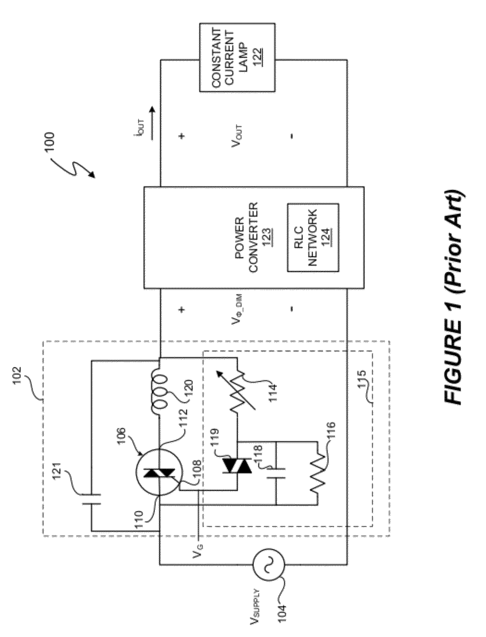
a multi-mode, dimmer technology, applied in the field of electronics, can solve the problems of inefficient power converter b>123/b> with the rlc network, edge dimmer 102/b> not operating ideally,

Inactive Publication Date: 2012-03-01
SIGNIFY HLDG BV
View PDF2 Cites 95 Cited by
  • Summary
  • Abstract
  • Description
  • Claims
  • Application Information

AI Technical Summary

Benefits of technology

[0025]In another embodiment of the present invention, an apparatus includes a a controller configured to generate a first signal for a power converter system upon occurrence of a leading edge of a dimmer input voltage. Gener

Problems solved by technology

However, in many circumstances, the leading edge dimmer 102 does not operate ideally.
The power conver

Method used


Image

  • Multi-Mode Dimmer Interfacing Including Attach State Control
  • Multi-Mode Dimmer Interfacing Including Attach State Control
  • Multi-Mode Dimmer Interfacing Including Attach State Control

Examples


Embodiment Construction

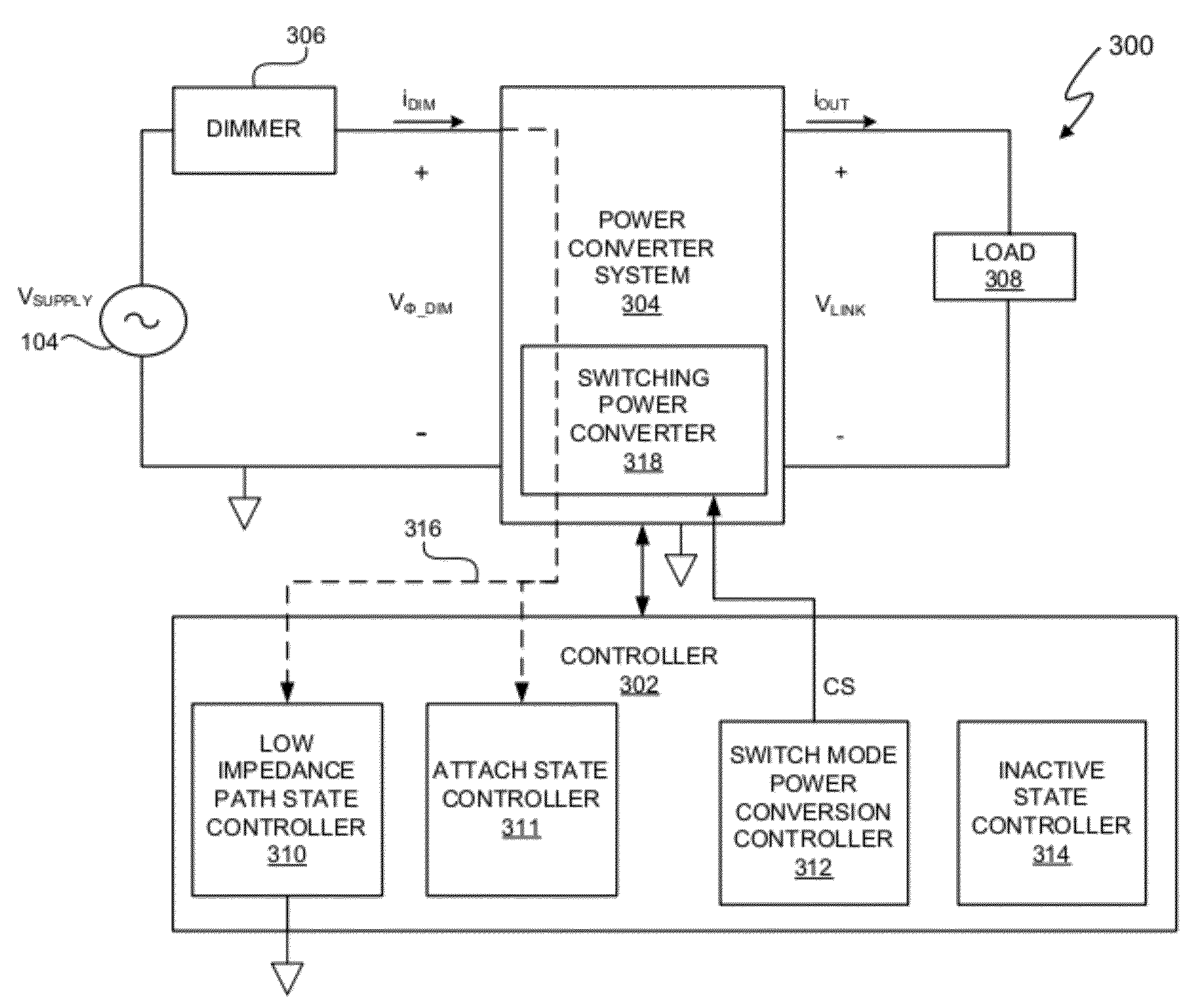
[0057]In at least one embodiment, a system and method includes a controller that is configured to coordinate (i) a low impedance path for a dimmer current, (ii) attaching a dimmer to an interface of a power converter system at the leading edge of a phase-cut, rectified input voltage, (iii), control of switch mode power conversion, and (iv) an inactive state to, for example, reduce the dimmer current while allowing a dimmer to function normally from cycle to cycle of an alternating current (AC) supply voltage. In at least one embodiment, the dimmer functions normally when the dimmer conducts at a correct phase angle indicated by a dimmer input setting and avoids prematurely resetting while conducting. In at least one embodiment, by coordinating functions (i), (ii), (iii), and (iv), the controller controls a power converter system that is compatible with a triac-based dimmer. In at least one embodiment, the controller coordinates functions (i), (ii), (iii), and (iv) in response to a p...


PUM


Abstract

A system and method includes a controller that is configured to coordinate (i) a low impedance path for a dimmer current, (ii) attaching a dimmer to a power converter system at the leading edge of a phase-cut, rectified input voltage, (iii), control of switch mode power conversion, and (iv) an inactive state to, for example, reduce the dimmer current while allowing a dimmer to function normally from cycle to cycle of an alternating current (AC) supply voltage. In at least one embodiment, the dimmer functions normally when the dimmer conducts at a correct phase angle indicated by a dimmer input setting and avoids prematurely resetting while conducting. In at least one embodiment, by coordinating functions (i), (ii), (iii), and (iv) the controller controls a power converter system that is compatible with a triac-based dimmer.

Description

CROSS-REFERENCE TO RELATED APPLICATION[0001]This application claims the benefit under 35 U.S.C. §119(e) and 37 C.F.R. §1.78 of U.S. Provisional Application No. 61 / 376,504, filed Aug. 24, 2010, and entitled “Multi-Mode Dimmer Interface for Lighting Boost Controller” and is incorporated by reference in its entirety.BACKGROUND OF THE INVENTION[0002]1. Field of the Invention[0003]The present invention relates in general to the field of electronics, and more specifically to a method and system for providing multi-mode interfacing to a dimmer including controlling an interface to a dimmer during an attach state of a dimming cycle of the dimmer. In at least one embodiment, an attach state occurs during an initial charge transfer period of a leading edge, triac-based dimmer.[0004]2. Description of the Related Art[0005]Electronic systems utilize dimmers to modify output power delivered to a load. For example, in a lighting system, dimmers provide an input signal to a lighting system, and the...

Claims


Application Information

Patent Timeline
IPC IPC(8): H05B37/02H05B44/00
CPCH05B33/0815Y10S315/04H05B37/02H05B39/044H05B45/3575Y02B20/00H05B47/10H05B45/38H05B47/165H05B45/39H05B45/397Y02B20/30
Inventor KING, ERIC J.MELANSON, JOHN L.
Owner SIGNIFY HLDG BV
Why Eureka
Try Eureka