Inkjet printing apparatus and inkjet printing method
a technology of inkjet printing and printing apparatus, which is applied in the direction of printing and other printing apparatus, can solve the problems of insufficient enhancement of uniform glossiness in the same image, and achieve the effect of high uniformity
- Summary
- Abstract
- Description
- Claims
- Application Information
AI Technical Summary
Benefits of technology
Problems solved by technology
Method used
Image
Examples
first embodiment
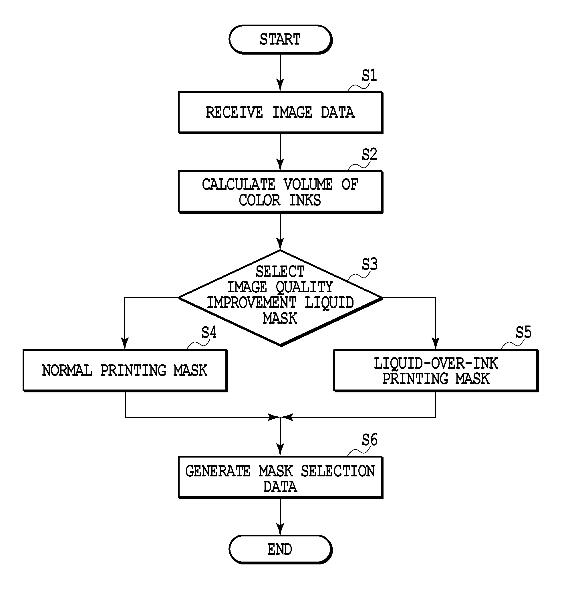
[0107]FIG. 12 is a flow chart showing a flow of processing that selects a mask pattern for the image quality improvement liquid according to the volume of the color inks applied to a predetermined area based on the image data. In the diagram, step S1 receives print data for each color ink in the predetermined area. Step S2 calculates the volume of color inks to be ejected. Further, steps S3-S5 determine the kind of image quality improvement liquid mask to be used in the print area of the print data. Step S6 generates data for selecting an image quality improvement liquid mask to be used (mask selection data).
[0108]At step S1, the print data in a unit area uses the 4×4 binary areas (600 dpi×600 dpi) of FIG. 10, which constitutes one pixel area, as a unit area. At step S2, the volume of inks ejected onto the unit area actually refers to a sum of volumes of different color inks applied, calculated based on the print data generated by the print data generation process J0006 of FIG. 8 (h...
second embodiment
[0117]Next, a second embodiment of this invention will be described. The second embodiment is basically similar to the first embodiment, except for the characteristic functions of the second embodiment described below. Of the image quality improvement liquid masks used in the first embodiment, the liquid-over-ink printing mask has a higher duty in the latter half scans than the normal printing mask. In the second embodiment, masks shown in FIGS. 15A-15C are used in combination to more efficiently control the gloss level and image clarity.
[0118]That is, in the second embodiment, the normal printing mask M21, which applies the image quality improvement liquid in the same scan that completes an image with color inks, and the liquid-over-ink printing mask M22, which applies the image quality improvement liquid following the scan that has completed an image with color inks, are used in combination. FIG. 15A schematically shows the normal printing mask M21 and its duty; FIG. 15B schematic...
third embodiment
[0121]Next, a third embodiment of this invention will be described. The third embodiment is basically similar to the first embodiment, except for the characteristic functions of the third embodiment. In the first embodiment, the method of applying the image quality improvement liquid is chosen according to the volume of inks applied to a unit area. In the third embodiment, on the other hand, the selection of the image quality improvement liquid application method is made according to the number of inks used for the printing in the unit area, i.e., depending on whether the inks printed in the unit area are primary colors, secondary colors or tertiary colors, as well as the volume of color inks applied.
[0122]FIG. 16 is a table showing a relation among the number of inks used to print an image in predetermined area, the volume of inks applied and the mask to be selected. An area printed with a greater number of inks tends to have a lower image clarity. So, for areas that are printed wi...
PUM
 Abstract
Description
Claims
Application Information
 - R&D
- Intellectual Property
- Life Sciences
- Materials
- Tech Scout
- Unparalleled Data Quality
- Higher Quality Content
- 60% Fewer Hallucinations
Browse by: Latest US Patents, China's latest patents, Technical Efficacy Thesaurus, Application Domain, Technology Topic, Popular Technical Reports.
© 2025 PatSnap. All rights reserved.Legal|Privacy policy|Modern Slavery Act Transparency Statement|Sitemap|About US| Contact US: help@patsnap.com


