
Road departure warning system

a warning system and road technology, applied in the field of vehicle human-machine interfaces, can solve the problems of preventing the use of these systems in non-automobile vehicles, on low-speed roads, sidewalks, and major causes of vehicle injuries and fatalities

Inactive Publication Date: 2012-03-01
HONDA MOTOR CO LTD
View PDF24 Cites 83 Cited by
  • Summary
  • Abstract
  • Description
  • Claims
  • Application Information

AI Technical Summary

Benefits of technology

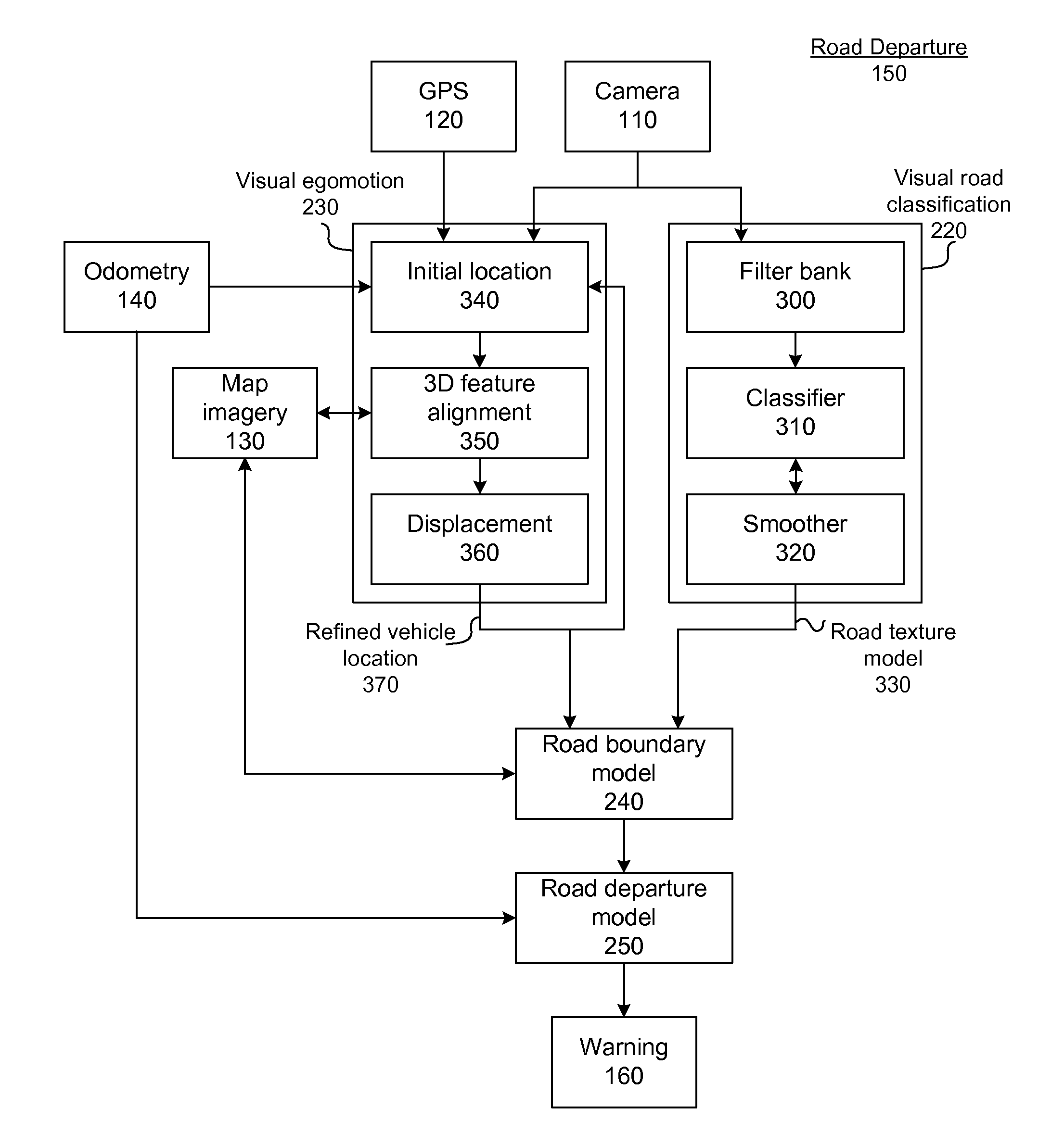
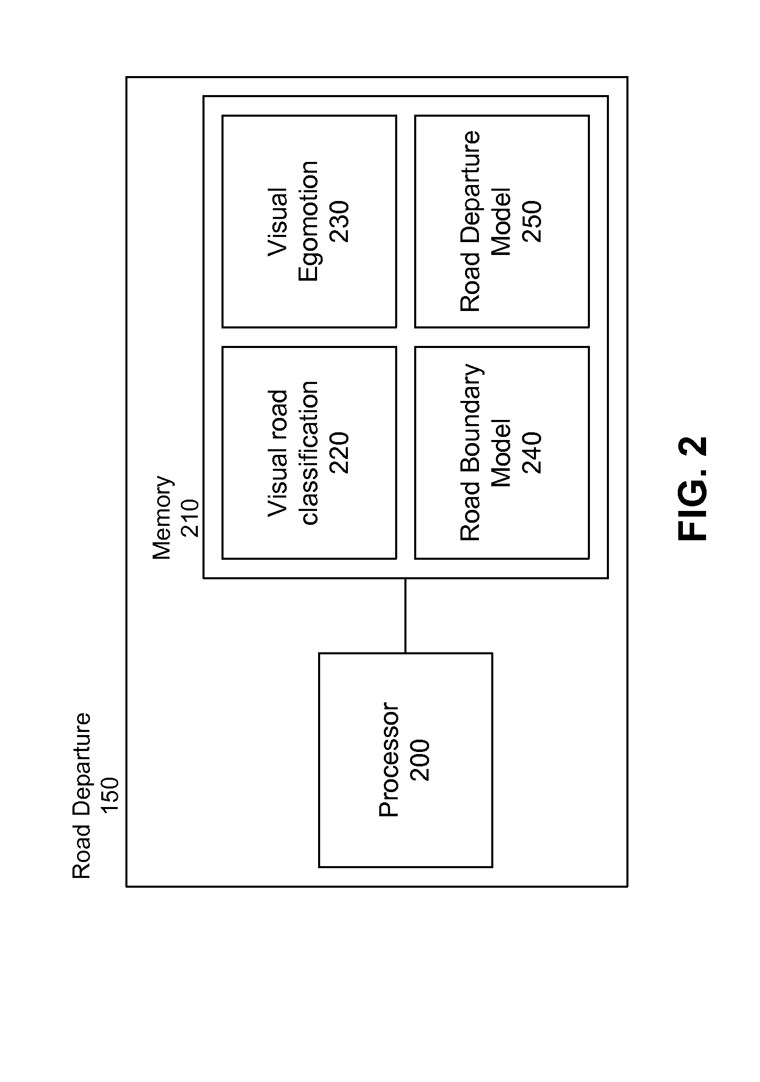
The patent describes a system that uses a camera to create a model of the road surface and the vehicle's location on it. This model is then used to create a warning system that alerts the driver when they are approaching a road boundary or when there is a high likelihood of a road departure. The system uses a filter bank to process the camera image and map imagery to create the road texture model. The system can also use visual cues from the vehicle's surroundings to refine the vehicle's location. Overall, the system improves safety by providing advanced warnings to drivers and reducing the likelihood of accidents.

Problems solved by technology

Road departures comprise a major cause of vehicle injuries and fatalities each year.
In addition, many previous road and lane departure systems only work for vehicles travelling above a certain speed.
This precludes the use of these systems in non-automobile vehicles and on low-speed roads, sidewalks, paths or other roads in which high speeds are dangerous or aren't possible.
Additional road and lane departure systems rely on multiple-meter Global Positioning System (GPS) signals, which are only accurate to within several meters, which limits the ability of these systems to provide road departure warnings early enough to be useful to the operator of a vehicle.
Further, relying on multiple-meter accuracy for departure warnings results in false-positive warnings, which are annoying to drivers.
Such false-positive warnings may cause the operator of a vehicle to disable the warnings, thereby nullifying the effectiveness of the warnings, or may cause a consumer to avoid purchasing a vehicle equipped to provide such warnings entirely.

Method used


Image

  • Road departure warning system
  • Road departure warning system
  • Road departure warning system

Examples


Embodiment Construction

Road Departure Warning System Overview

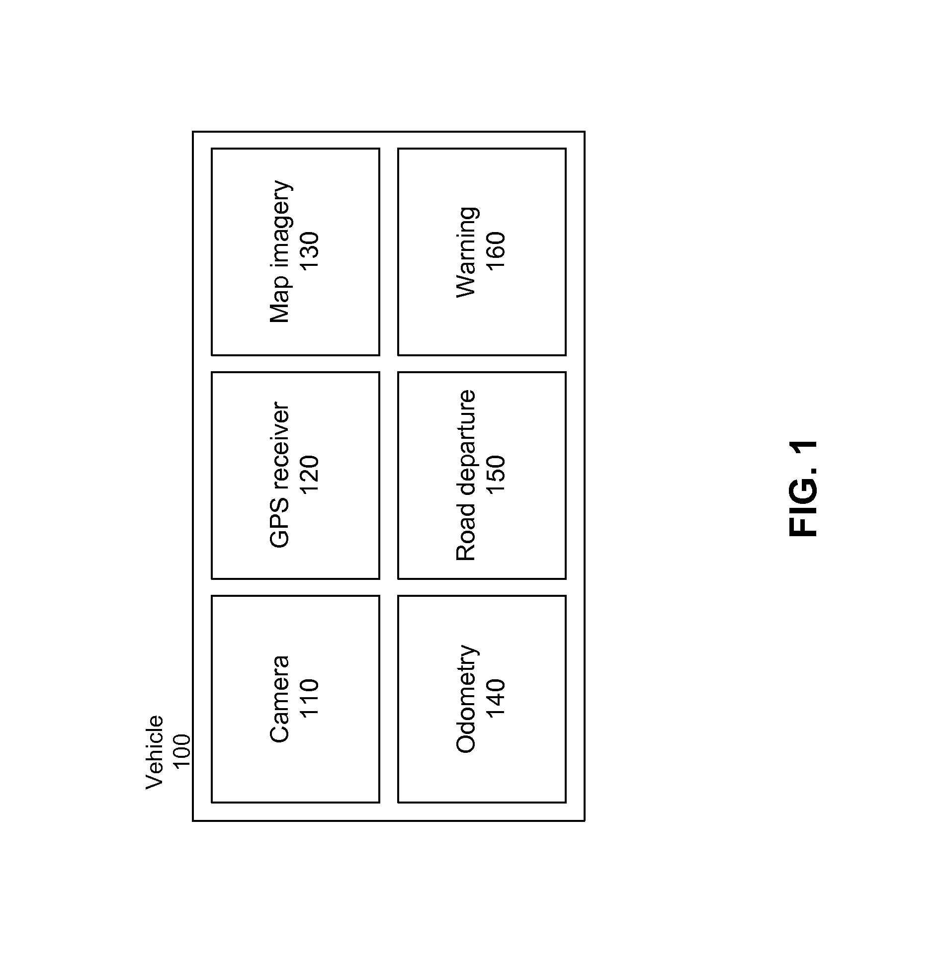
[0021]FIG. 1 illustrates a vehicle environment for a road departure warning system in accordance with one embodiment. The road departure warning system described herein is implemented in a vehicle 100. The vehicle 100 may be a passenger automobile, a utility vehicle, a semi-truck, a motorcycle, a tractor, a bus or van, an ambulance or fire truck, or any vehicle traditionally driven on roadways. Alternatively, the vehicle 100 may be a personal mobility vehicle, such as a scooter, an electric wheelchair, a drivable cart, or any other low-speed vehicle. In addition, the vehicle 100 may be an off-road vehicle, a snowmobile, or any other type of vehicle capable of driving roads, paths, trails, sidewalks, parking lots, or any other type of route capable of being navigated (collectively referred to herein as “roads”).

[0022]The vehicle 100 includes a camera 100, a GPS receiver 120, a map imagery module 130, an odometry module 140, a road departure modul...


PUM


Abstract

The prevention of vehicle accidents is targeted. A road texture model is created based on a vehicle camera image. An initial vehicle location estimate is determined, and map imagery is obtained based on this location estimate. A refined vehicle location is determined using visual egomotion. In particular, 3D features of the vehicle image and the retrieved map imagery are identified and aligned. A map image is selected based on this alignment, and the location associated with the map image is modified by a displacement between the selected map image and the vehicle image to produce a refined vehicle location. A road boundary model is created based on the road texture model and the refined vehicle location, and a road departure model is created based on the road boundary model and vehicle odometry information. The operator of the vehicle is warned of a road departure based on the road departure model.

Description

RELATED APPLICATIONS[0001]This application claims the benefit of U.S. Provisional Application No. 61 / 378,298, filed Aug. 30, 2010 the content of which is incorporated by reference herein in its entirety.FIELD OF THE INVENTION[0002]The exemplary embodiments relate to the field of vehicle human-machine interfaces and more particularly to a warning system for warning the operator of a vehicle of potential road departures.BACKGROUND OF THE INVENTION[0003]Vehicle safety consistently remains a cause for concern amongst vehicle manufacturers and consumers. Road departures comprise a major cause of vehicle injuries and fatalities each year. In order to address this issue, manufactures have included active stability control systems and related approaches in vehicles to prevent vehicles from driving outside the boundaries of the road. Although these approaches contain numerous advances designed to increase vehicle safety, the operator's actions are often the ultimate arbiter of whether a vehi...

Claims


Application Information

Patent Timeline
Patent Type & Authority Applications(United States)
IPC IPC(8): H04N13/02G08G1/123H04N7/18
CPCG06T2207/10016G06T2207/20081G06T2207/30256G06T7/74G06T7/41G06V20/588H04N13/00
Inventor GUPTA, RAKESHRANGANATHAN, ANANTHLIM, JONGWOO
Owner HONDA MOTOR CO LTD
Learn More