


Quick Research
Generate reliable direction feasibility study reports for your R&D in just a few steps.

Technical Q&A
Discover and master advanced knowledge NOW. Basics, ideas, possibilities, all at once.

Find Solutions
As an expert in R&D theories, this can generate solutions to your technical problems instantly.

Evaluate Feasibility
Analyze your overall solution with one click, know your potential R&D risks in advance.

Monitor Landscape
Get weekly tech updates, stay abreast of the latest tech innovations and key insights.
Pupil detection device and pupil detection method
a detection device and pupil technology, applied in the field of pupil detection apparatus and pupil detection method, can solve problems such as difficulty in performing stable pupil detection
- Summary
- Abstract
- Description
- Claims
- Application Information
AI Technical Summary
Benefits of technology
Problems solved by technology
Method used
Image

Examples
embodiment 1
Configuration of Pupil Detection Apparatus
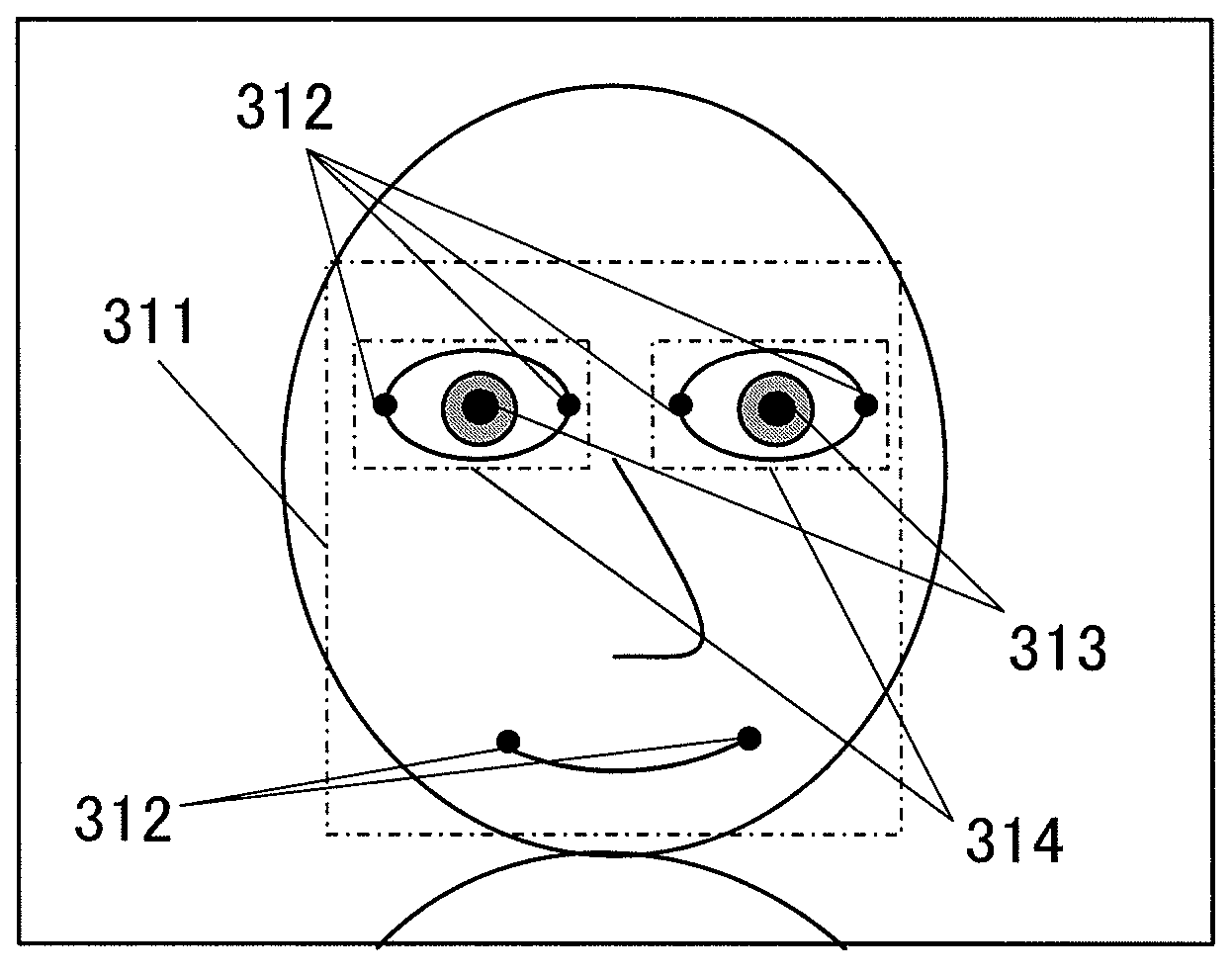
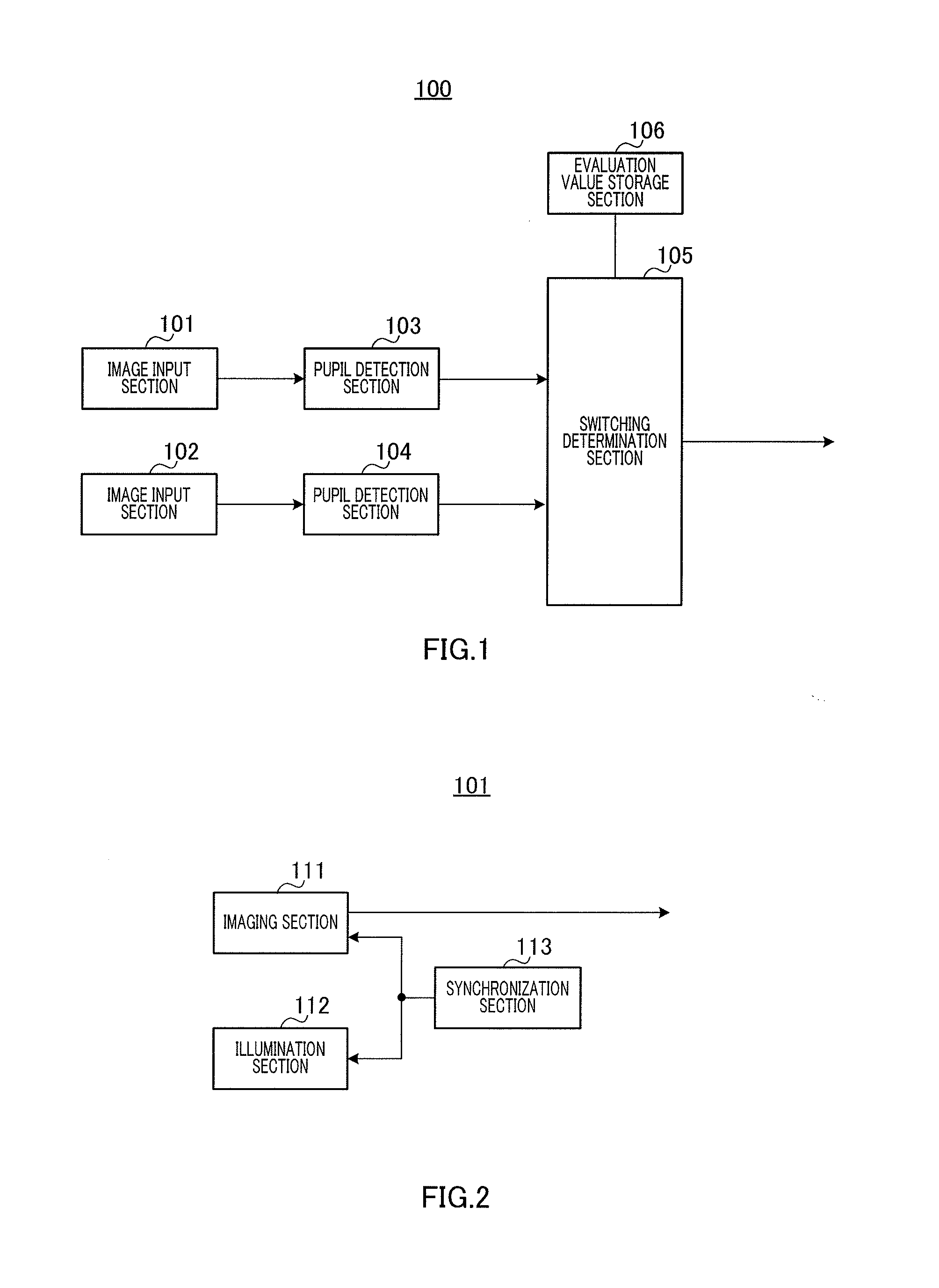
[0030]FIG. 1 is a block diagram showing the configuration of pupil detection apparatus 100 according to Embodiment 1 of the present invention. Pupil detection apparatus 100 is, for example, installed in the passenger compartment of a vehicle, and used connected to an alarm apparatus. This alarm apparatus detects a line of sight of a driver based on a pupil detection apparatus 100 detection result, and alerts the driver with a warning if the driver does not look straight ahead for a long period of time. Below, a case in which pupil detection apparatus 100 is installed in the passenger compartment of a vehicle, in particular, will be described as an example.
[0031]In FIG. 1, pupil detection apparatus 100 has image input sections 101 and 102, pupil detection sections 103 and 104, switching determination section 105, and evaluation value storage section 106.
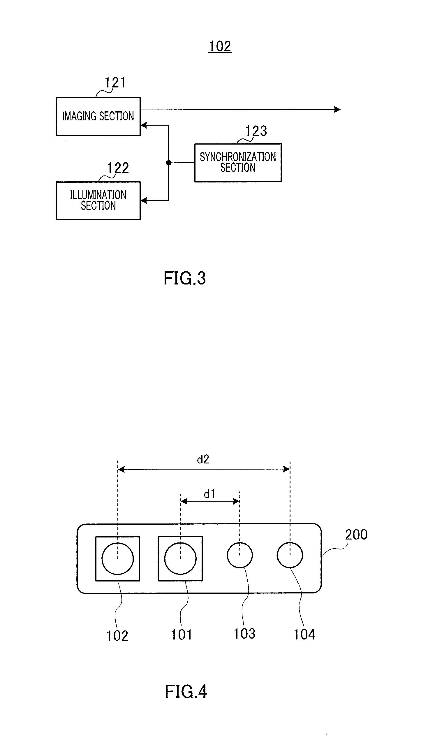
[0032]Image input sections 101 and 102 emit light and illuminate an imaging target (that i...
embodiment 2
[0101]In Embodiment 2, a pupil detection result is selected based on an illuminance coefficient in addition to calculated red-eye occurrence intensity and a correlation characteristic of red-eye occurrence intensity and a pupil detection accuracy rate.
[0102]FIG. 13 is a block diagram showing the configuration of pupil detection apparatus 700 according to Embodiment 2 of the present invention. In FIG. 13, pupil detection apparatus 700 has luminometer 701, switching determination section 702, and evaluation value storage section 703.
[0103]Luminometer 701 measures illuminance at the time of imaging by image input sections 101 and 102, and outputs measured illuminance to evaluation value storage section 703. Luminometer 701 is installed in the vicinity of a driver's face, or in a position where it can measure illuminance in a driver's gaze direction.
[0104]Switching determination section 702 calculates “red-eye occurrence intensity” from target image data received from image input sectio...
embodiment 3
[0122]In Embodiment 3, correlation characteristics corresponding to a plurality of modes are prepared, and pupil detection reliability is calculated based on a correlation characteristic corresponding to a selected mode.
[0123]FIG. 17 is a block diagram showing the configuration of pupil detection apparatus 900 according to Embodiment 3 of the present invention. In FIG. 17, pupil detection apparatus 900 has mode selection section 901 and switching determination section 902.
[0124]Mode selection section 901 selects one mode from among a prepared plurality of modes. This plurality of modes includes, for example, a first mode in which a target person is wearing sunglasses and a second mode in which a target person is not wearing sunglasses. Information relating to the selected mode is output to switching determination section 902.
[0125]Switching determination section 902 calculates “red-eye occurrence intensity” from target image data received from image input section 101 and target imag...
PUM
 Abstract
Description
Claims
Application Information
 - R&D Engineer
- R&D Manager
- IP Professional
- Industry Leading Data Capabilities
- Powerful AI technology
- Patent DNA Extraction
Browse by: Latest US Patents, China's latest patents, Technical Efficacy Thesaurus, Application Domain, Technology Topic, Popular Technical Reports.
© 2024 PatSnap. All rights reserved.Legal|Privacy policy|Modern Slavery Act Transparency Statement|Sitemap|About US| Contact US: help@patsnap.com