Driver module and electronic device

a technology of electronic devices and driving modules, which is applied in the direction of instruments, other domestic objects, optical elements, etc., can solve the problems of difficult to decrease the diameter of the needle is likely to be clogged, and the adhesion agent is likely to block the needle, etc., to achieve high quality, reduce the cost, and the effect of high quality

Inactive Publication Date: 2012-03-01
SEIKO INSTR INC
View PDF2 Cites 15 Cited by
  • Summary
  • Abstract
  • Description
  • Claims
  • Application Information

AI Technical Summary

Benefits of technology

[0020]Moreover, a product in which the adhesive agent is applied to the outer surface of the cover results in a defective product of which the dimensions are outside the allowable product dimension range, which decreases the yield ratio.
[0050]Moreover, according to the electronic device of the invention, since it has the driving module, it is possible to provide an electronic device which has high quality and is not expensive.

Problems solved by technology

In addition, since the adhesive agent requires viscosity of a certain level or more, the adhesive agent is likely to clog the needle when the needle diameter decreases.
Thus, the above-mentioned problems occur.
If an adhesive agent having low viscosity is used to enable the use of a narrower needle diameter, the applied adhesive agent may flow into the inner side of a product and cause malfunction.
Therefore, viscosity of a certain level or more is required for an adhesive agent, and accordingly, it is difficult to decrease the needle diameter.

Method used


Image

  • Driver module and electronic device
  • Driver module and electronic device
  • Driver module and electronic device

Examples


Embodiment Construction

[0073](Driving Module)

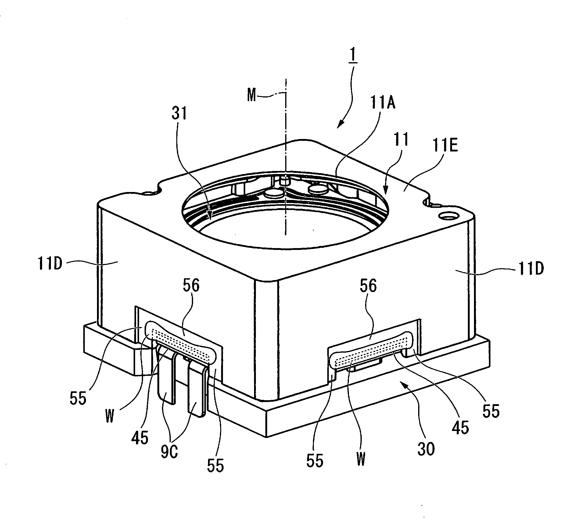
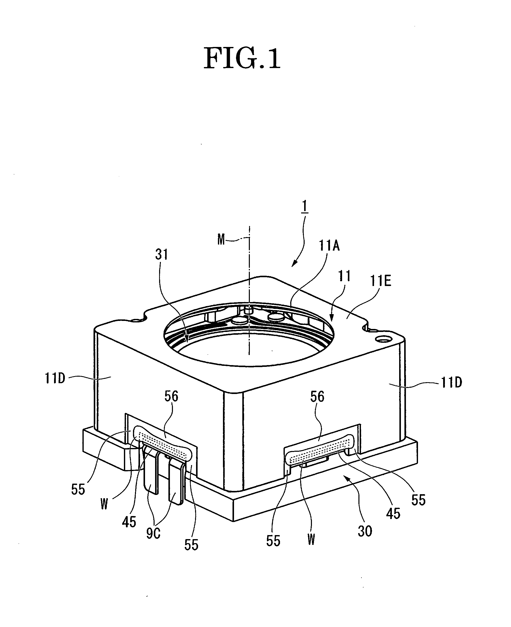
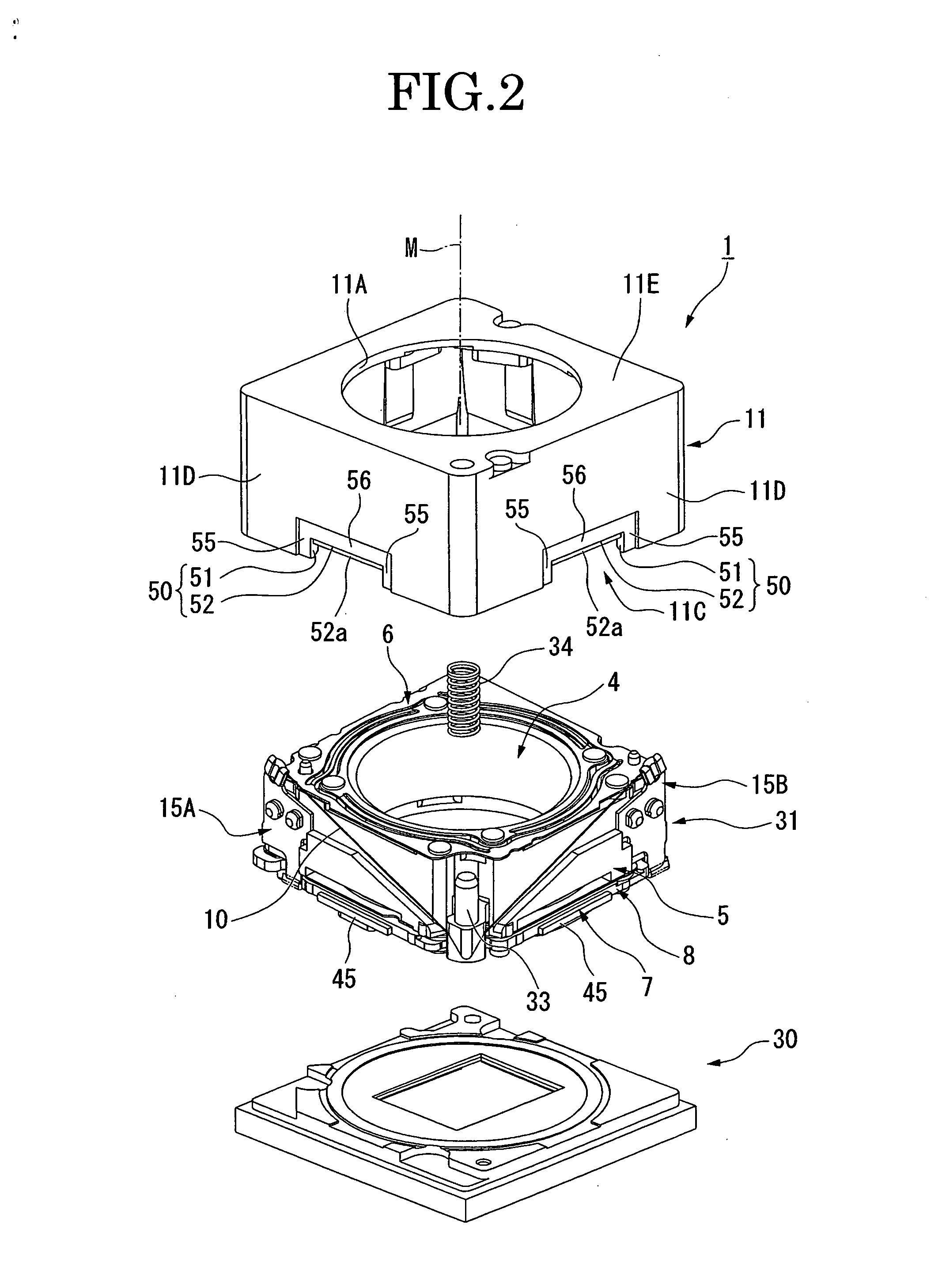
[0074]Hereinafter, an embodiment of a driving module according to the invention will be described with reference to FIGS. 1 to 16. In the present embodiment, a driving module that drives an imaging lens unit in a camera will be described as an example. Moreover, a case in which a shape memory alloy wire is used as an example of an actuator that drives the lens unit will be described as an example.

[0075]In the present embodiment, in some drawings, for better understanding of the drawings, illustrations of constituent members such as a lens unit 12 shown in FIG. 5 are appropriately omitted.

[0076]Moreover, symbol M in drawings, for example, FIG. 1, is an imaginary axial line of a driving module 1 which is identical to the optical axis of the lens unit 12, and indicates a direction in which a lens frame 4 described later is driven. In the following description, the positions and directions of exploded respective components are sometimes referenced based on the posi...


PUM

PropertyMeasurementUnit
depthaaaaaaaaaa
thicknessaaaaaaaaaa
flexibilityaaaaaaaaaa

Abstract

A driving module 1 includes: a support member 5 fixed on a base substrate 8; a driven member 4 arranged so as to be movable back and forth in relation to the support member; driving means 10 for driving the driven member; and an exterior cover 11 attached so as to cover the support member, the driven member, and the driving means and attached and fixed to the base substrate. A projection piece 45 which is accommodated in a concave accommodation portion 50 is formed on the base substrate. The base substrate and the exterior cover are attached and fixed by an adhesive agent filled in a first filling region which is defined between a lateral inner wall 51 and the projection piece and a second filling region which is defined between an upper inner wall 52 and the projection piece. A lateral step portion 55 which is formed to be recessed in a state of being continuous to the lateral inner wall of the concave accommodation portion and to which the adhesive agent running out of the first filling region is guided is formed on the exterior cover.

Description

BACKGROUND OF THE INVENTION[0001]1. Field of the Invention[0002]The invention relates to a driving module and an electronic device.[0003]Particularly, the invention relates to a driving module which is suitable for driving an optical system and a movable member to perform focus position adjustment and which is suitably used as an actuator, and an electronic device.[0004]2. Description of the Related Art[0005]In the related art, in compact electronic devices such as a mobile camera phone, various driving modules which perform driving using the flexibility of a shape memory alloy wire have been proposed in order to drive a driven member such as an imaging lens unit to perform autofocus, zooming, and the like (see JP-A-2009-128708 (Patent Reference 1)).[0006]The driving module disclosed in Patent Reference 1 includes a support member fixed to the lower module plate, a lens frame capable of moving back and forth in a certain direction with respect to the support member, a plate spring m...

Claims


Application Information

Patent Timeline
Patent Type & Authority Applications(United States)
IPC IPC(8): G02B7/04G02B7/02
CPCB29C65/08B29C65/4855B29C65/54B29C65/606B29C66/304B29C66/322B29C66/5346B29C66/54B29C66/742B29C66/74283B29C66/81B29L2031/3481G02B7/025G02B7/08G02B13/001B29C65/18B29K2069/00B29K2105/0079
Inventor KOTANAGI, SUSUMU
Owner SEIKO INSTR INC
Why Eureka
Try Eureka