Methods, Apparatuses for Providing Secure Fiber Optic Connections

a fiber optic connection and fiber optic cable technology, applied in the direction of optical elements, instruments, manufacturing tools, etc., can solve the problems of network downtime, improper connection or disconnection of fiber optic cables to fiber optic adapter panels or modules, and inadvertent or malicious connections or disconnections

Inactive Publication Date: 2012-03-01
CORNING OPTICAL COMM LLC
View PDF8 Cites 77 Cited by
  • Summary
  • Abstract
  • Description
  • Claims
  • Application Information

AI Technical Summary

Benefits of technology

[0013]The disclosed apparatuses and method allow fiber optic connectors to be locked in or out of a fiber optic adapter panel or other fiber optic module. One advantage of the disclosed locking mechanism is that it may be used for any standard fiber optic connector (including, but not limited to SC, LC, ST, MTP, etc.), which reduces the need for different solutions. In addition, the locking apparatus can be used as both a lock-in and lock-out device, instead of requiring different devices for each function.

Problems solved by technology

Given the number of optical interconnections in the LCPs or FDTs, one concern is that improper connections or disconnections of fiber optic cables to the fiber optic adapter panels or modules may occur.
The improper connections or disconnections may be inadvertent or malicious.
Inadvertent connections or disconnections can cause network downtime.
Malicious connections or disconnections can facilitate traffic filtering, sniffing, or mirroring, and is a security risk.
However, only fairly recently has this technology been available at affordable costs.
This represents a security risk if not all ports are used or connected.

Method used


Image

  • Methods, Apparatuses for Providing Secure Fiber Optic Connections
  • Methods, Apparatuses for Providing Secure Fiber Optic Connections
  • Methods, Apparatuses for Providing Secure Fiber Optic Connections

Examples


Embodiment Construction

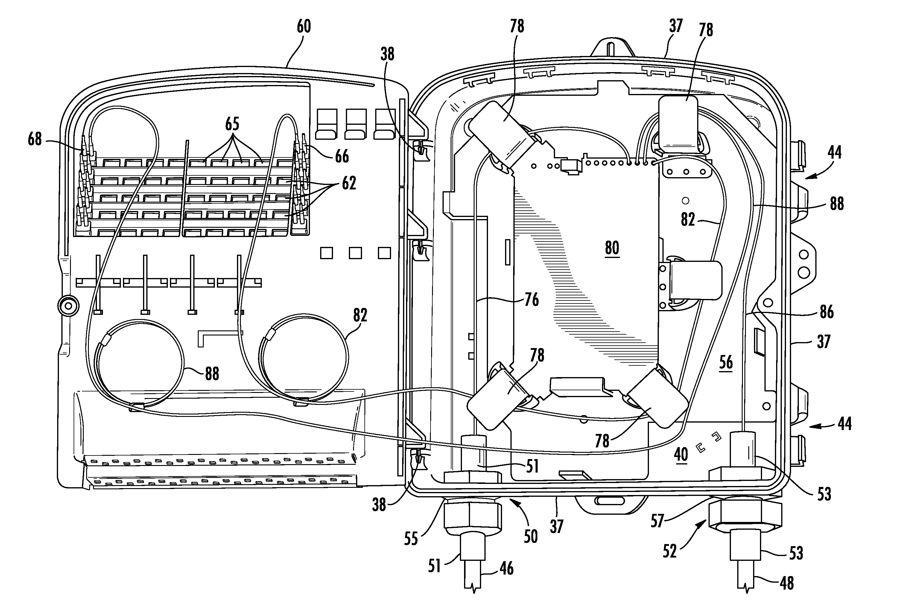
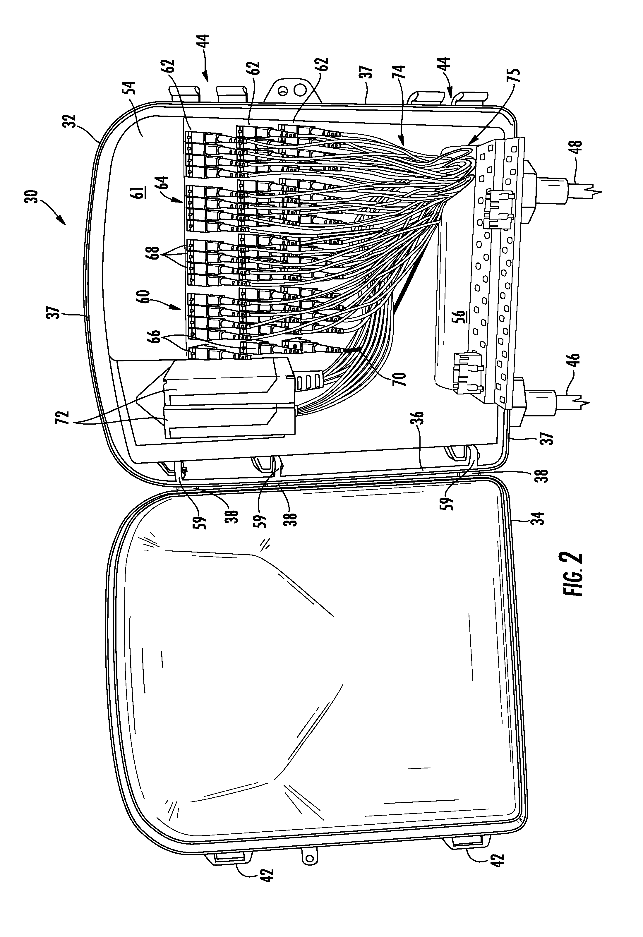
[0010]Embodiments disclosed in the detailed description include methods and apparatuses for providing secure fiber optic connections. In this regard in one embodiment, a locking apparatus configured to secure a fiber optic adapter panel, a fiber optic module, or fiber optic connections is provided. The locking apparatus comprises a locking plate comprising at least one cut-out area and at least one finger portion. The locking plate is further configured to be adjustably positioned in a selected position such that when a fiber optic connector on an end of a fiber optic cable is connected to at least one fiber optic adapter, the fiber optic cable is allowed to pass through the cut-out area of the locking plate but the at least one finger portion of the locking plate does not allow the fiber optic connector to pass through the cut-out area of the locking plate. A lock disposed on the locking plate is configured to keep the locking plate in the selected position after the locking plate ...


PUM

PropertyMeasurementUnit
angleaaaaaaaaaa
degree of rotationaaaaaaaaaa
diameteraaaaaaaaaa

Abstract

Methods and apparatuses for providing secure fiber optic connections are disclosed. In one embodiment, a locking apparatus comprising a locking plate to secure fiber optic connections is disclosed. The locking plate is configured to be attached to a fiber optic adapter panel and adjustably positioned to a selected position such that when a fiber optic connector on the end of a fiber optic cable is connected to a fiber optic adapter on the fiber optic adapter panel, the fiber optic cable is allowed to pass through a cut-out area of the locking plate but a finger portion of the locking plate does not allow the fiber optic connector to pass through the cut-out area. A lock disposed on the locking plate is configured to keep the locking plate in the selected position. The locking apparatus may also be used to securely store unused or unconnected ports of an optical splitter in a separate enclosure, such as a parking lot compartment.

Description

BACKGROUND[0001]1. Technical Field[0002]The field of the disclosure relates to providing secure fiber optic connections, and in particular, including in or out of fiber optic adapter panels, fiber optic modules, fiber optic terminals, and / or parking lot compartments in fiber optic terminals.[0003]2. Technical Background[0004]To provide improved performance to subscribers, communication and data networks are increasingly employing optical fiber. The benefits of optical fiber are well known and include higher signal-to-noise ratios and increased bandwidth. To further improve performance, fiber optic networks are increasingly providing optical fiber connectivity all the way to end subscribers. These initiatives include various fiber-to-the-premises (FTTP), fiber-to-the-home (FTTH), and other fiber initiatives (generally described as FTTx).[0005]In this regard, FIG. 1 illustrates an exemplary fiber optic network 10. The fiber optic network 10 provides optical signals from switching poin...

Claims


Application Information

Patent Timeline
Patent Type & Authority Applications(United States)
IPC IPC(8): G02B6/46B23P21/00
CPCG02B6/3897G02B6/4463G02B6/4471G02B6/3616Y10T29/49947G02B6/3632G02B6/3636G02B6/3652G02B6/4452G02B6/3628G02B6/50
Inventor BARNES, RAY S.CUNNINGHAM, DAVE E.DEUTSCH, BERNHARD A.
Owner CORNING OPTICAL COMM LLC
Why Eureka
Try Eureka