
Method for monitoring wavelength-division multiplexed signal

a multiplexed signal and wavelength technology, applied in the direction of transmission monitoring, transmission monitoring/testing/fault-measurement systems, electrical equipment, etc., can solve the problems of interference, signal drift can be particularly problematic, and the electrical radiation signal can be undesired affected, so as to reduce the power amplitude of multiplexed guards, the effect of enhancing the error rate and low error ra

Inactive Publication Date: 2012-03-01
LOCKHEED MARTIN CORP
View PDF5 Cites 0 Cited by
  • Summary
  • Abstract
  • Description
  • Claims
  • Application Information

AI Technical Summary

Benefits of technology

The patent describes a method for monitoring a wavelength-division multiplexed (WDM) signal by generating a guard signal with a specific wavelength and power, and then multiplexing it with the signal to be monitored. The guard signal is designed to drift in response to changes in the signal, allowing for the measurement of signal drift and the detection of errors in the signal. The method can be used to monitor the health of optical signals in a WDM system. The technical effect of this patent is to provide a reliable and effective way to monitor WDM signals for errors and malfunctions.

Problems solved by technology

Electromagnetic radiation signals can be undesirably affected by signal drift.
For example, changes in temperature that can affect components of a system or overall breakdown of components leading to system failure can cause signal drift.
Signal drift can be particularly problematic if there are multiple signals sent at different wavelengths along the same connection.
When a signal drifts in a wavelength-division multiplexed signal, a signal drift of one channel, or wavelength, can cause that channel to drift into its adjacent channel causing interference.
For optical signals, interference is caused by leaking photons from the drifting channel to another channel.
Such interference can cause significant noise in a channel.
Noise causes error rates of a signal or channel.
A prolonged interference or substantial amount of interference can lead to unacceptable rise in the error rate.
Increased error rate can lead to the total loss of data on the channel.
However, there are several disadvantages of using a spectrum analyzer.
Spectrum analyzers require expensive equipment and may not be able to be integrated into some systems or solutions.
Further, the Nyquist frequency limit also may hinder perfect reconstruction of the signals from the waveform.
Further, use of these techniques may cause ghost signals, wherein certain frequency components are included in the output but were not part of the original signal.

Method used


Image

  • Method for monitoring wavelength-division multiplexed signal
  • Method for monitoring wavelength-division multiplexed signal
  • Method for monitoring wavelength-division multiplexed signal

Examples


Embodiment Construction

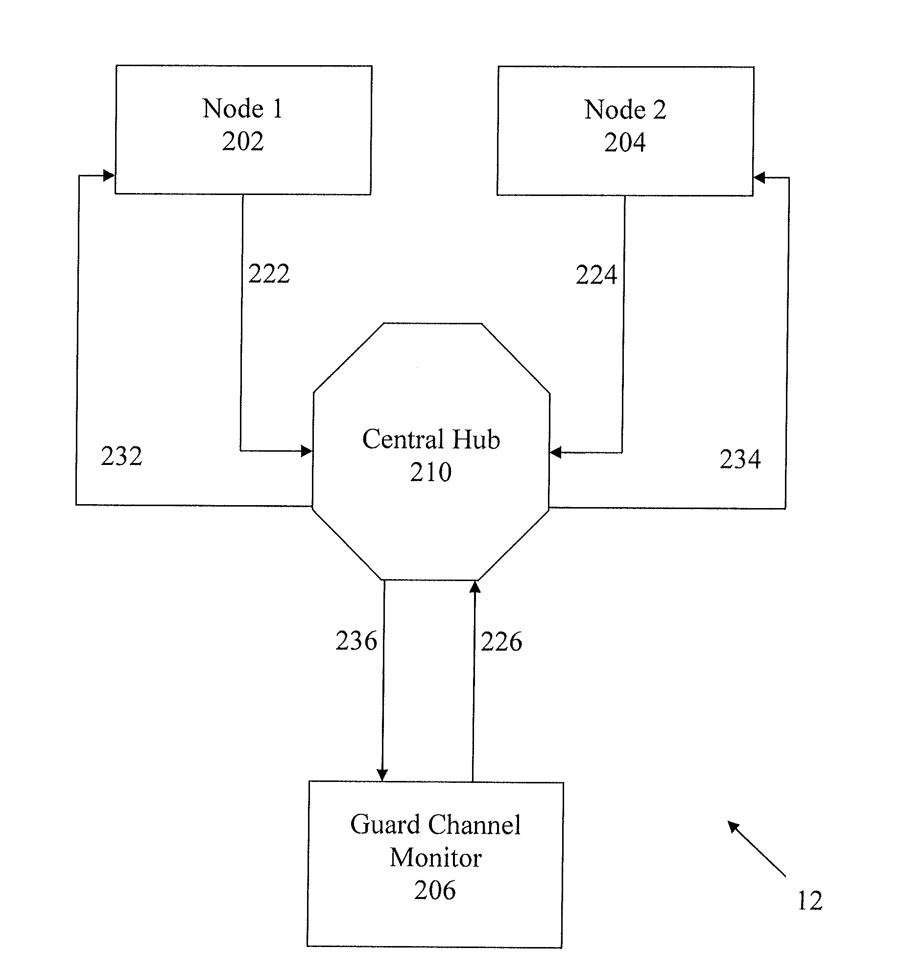
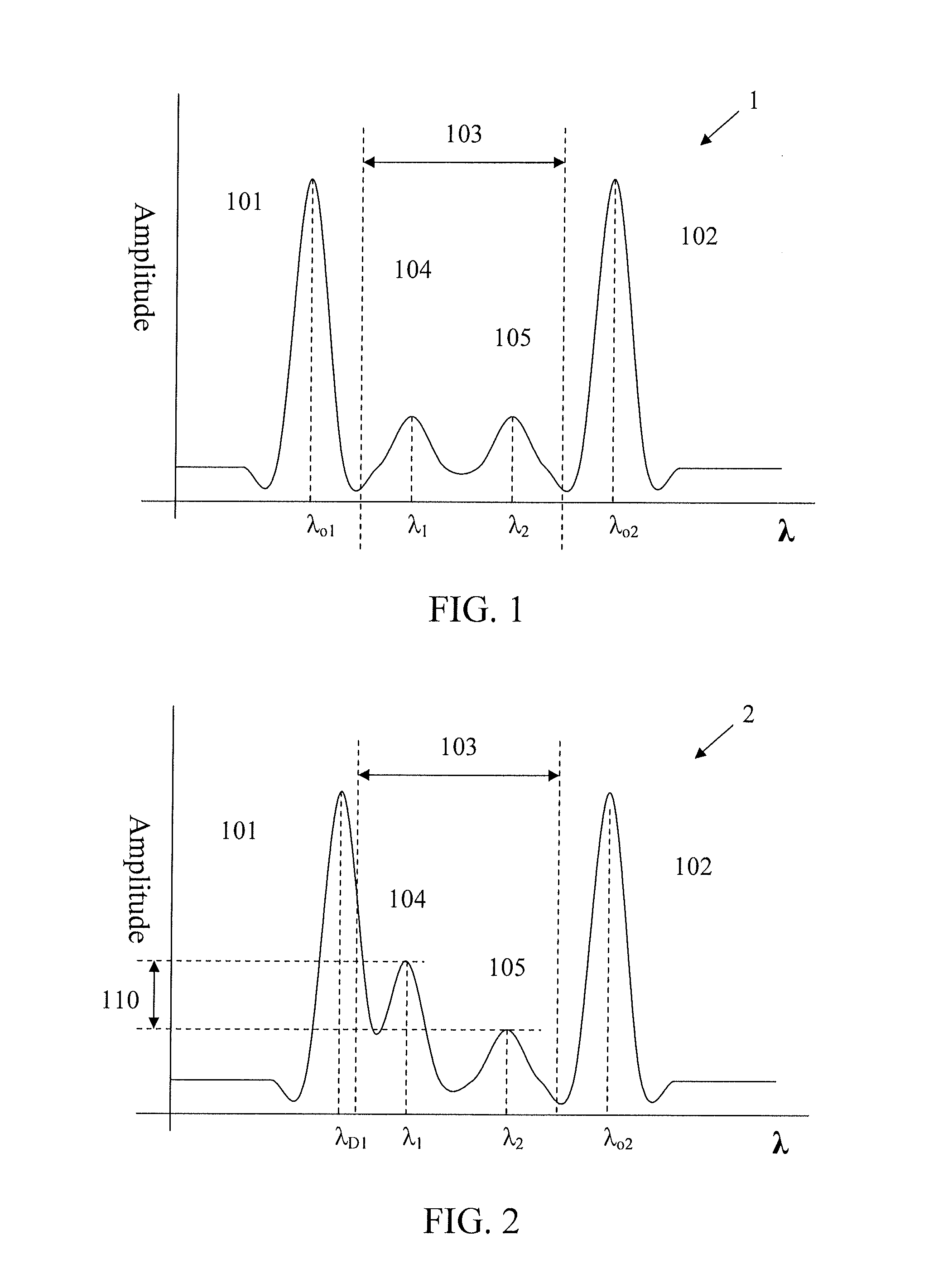
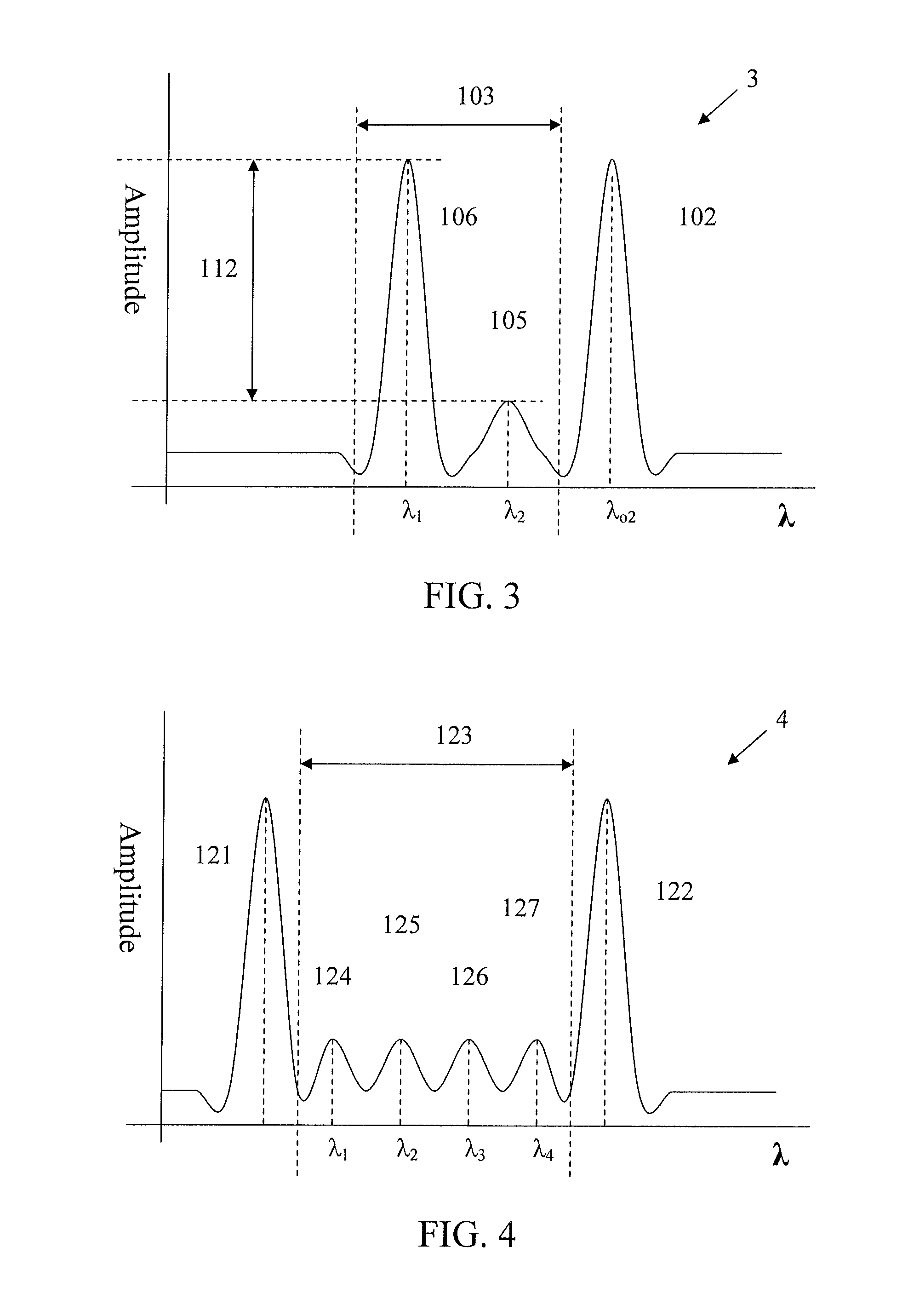
[0035]The term “wavelength-division multiplexing” is defined herein to include frequency division multiplexing (FDM). The term “signal” is defined to include electromagnetic radiation signals. Electromagnetic radiation signals include, for example, optical signals and radio signals. On a waveform, the term “signal” may also describe portions of the waveform that carries data. For example, in a wavelength-division multiplexed signal having a particular waveform having multiple peaks in amplitude, each of the peaks may be described as “signals” wherein each of the signals may also be described to have a channel, a carrier frequency, or associated wavelength. The term “signal drift” is defined herein to include carrier frequency drift. Objective signal, also known in the art as primary signal, is defined herein to include radio frequency signals that carry data. A guard signal may also carry data. The term channel describes a wavelength. Power amplitude is defined herein as a measurabl...


PUM


Abstract

A method for monitoring wavelength-division multiplexed (WDM) signal for detecting signal drift of objective signals, including generation of one or more objective signals and a guard signal. The guard signal has a wavelength that is within a range defined by a guard channel. The first and second objective signals and the guard signal are wavelength-division multiplexed to generate a wavelength-division multiplexed signal. The first objective signal, the second objective signal, and the guard signal are assigned to a first multiplexed objective channel, a second multiplexed objective channel, and a multiplexed guard channel, respectively. The wavelength-division multiplexed signal is received by a monitor and then the error rate of the multiplexed guard channel is determined.

Description

FIELD[0001]This description relates generally to detecting signal drift of a wavelength-division multiplexed signal by providing and monitoring a wavelength-division multiplexed signal.BACKGROUND[0002]Electromagnetic radiation signals can be undesirably affected by signal drift. Generally, signal drift, also known as frequency drift, is an unintended offset of a signal's carrier frequency from its nominal frequency. Because of the inverse relationship between frequency and wavelength, frequency offset can be described using a wavelength of the signal. There are several causes for signal drift. For example, changes in temperature that can affect components of a system or overall breakdown of components leading to system failure can cause signal drift.[0003]Signal drift can be particularly problematic if there are multiple signals sent at different wavelengths along the same connection. For example, optical signals having different carrier frequencies may be communicated along the sam...

Claims


Application Information

Patent Timeline
Patent Type & Authority Applications(United States)
IPC IPC(8): H04B17/00
CPCH04B2210/078H04B10/0775
Inventor SCHANTZ, HOWARD J.UHLHORN, BRIAN L.
Owner LOCKHEED MARTIN CORP
Learn More