Independent blade pitch control

a technology of independent blades and pitch control, which is applied in the direction of rotors, marine propulsion, vessel construction, etc., can solve the problems of increasing stress and strain on the blades, affecting the efficiency and life of the turbine, and using current turbines that use either no pitch control, etc., to achieve efficient and effective configuration and orientation

Inactive Publication Date: 2012-03-01
BLUESCOUT TECH INC
View PDF1 Cites 30 Cited by
  • Summary
  • Abstract
  • Description
  • Claims
  • Application Information

AI Technical Summary

Benefits of technology

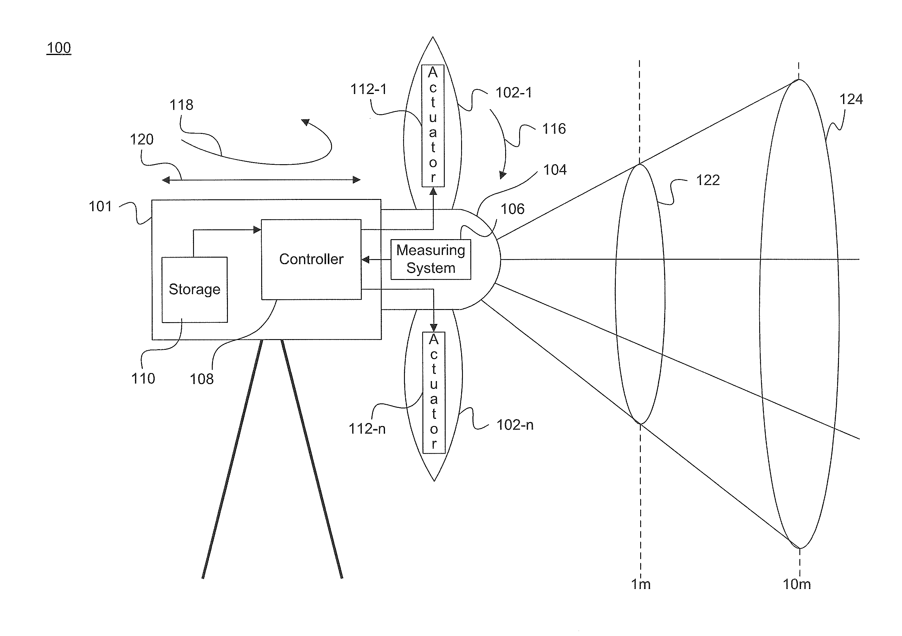
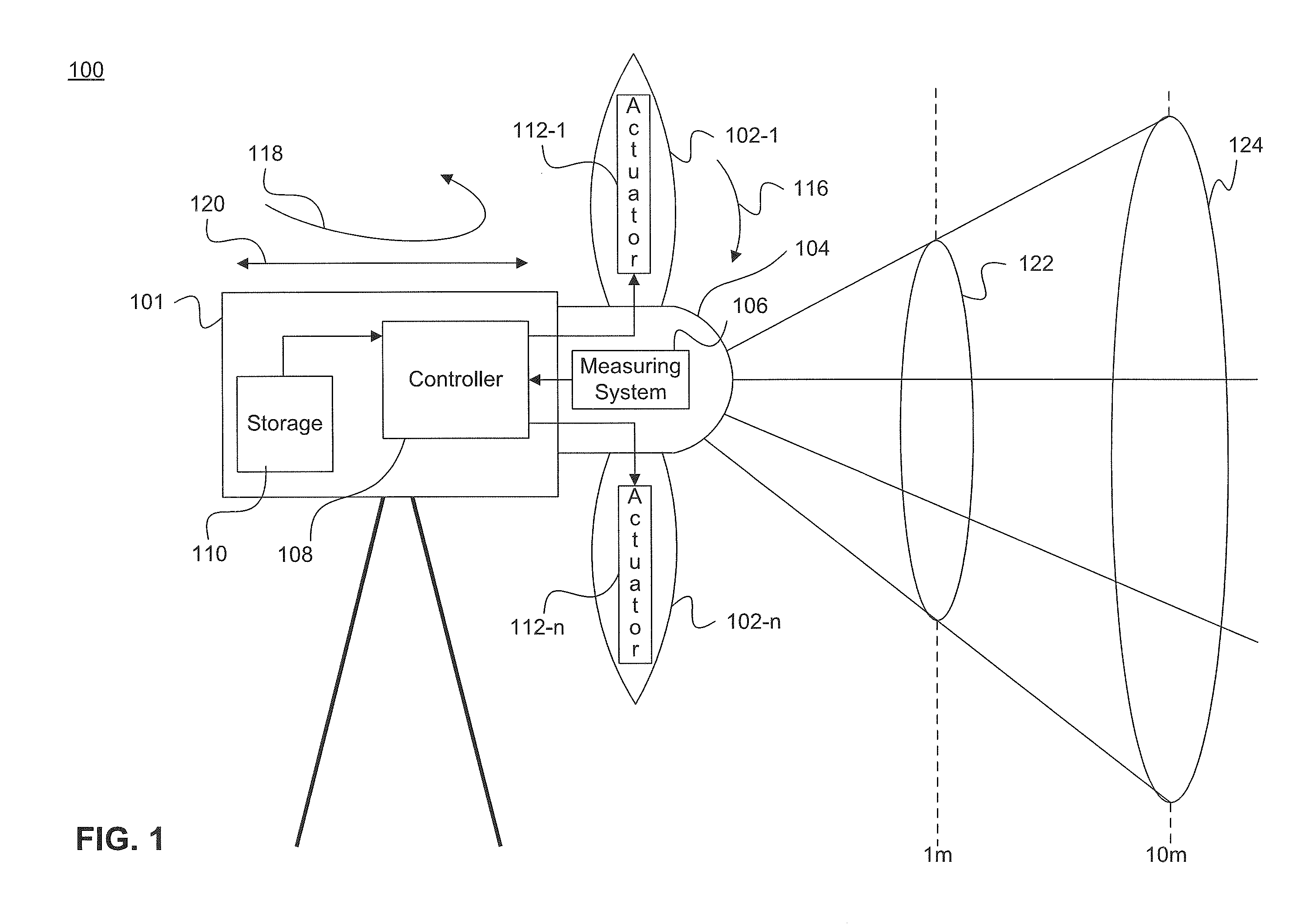
[0009]Therefore, what is needed is a system and method that can proactively and dynamically adjust a pitch of a blade of a turbine to more efficiently and effectively configure and orient the blade to travel through an inflow of wind.
[0014]Embodiments of the invention make it possible to increase the generation of electrical power from wind. Embodiments of the invention also make it possible to generate electrical power from wind in a more cost effective manner. Accordingly, embodiments of the invention materially contribute to the development of energy resources, as well as to the more efficient utilization of energy resources.

Problems solved by technology

However, current turbines use either no pitch control, or at most use reactive pitch control.
Both negatively effect efficiency and life of the turbines as the blades are not optimally positioned to travel through the incoming wind causing increased stress and strain on the blades.
Reactive compensation results in damage already being done to turbines before adjustments are made.
Also, reactive compensation usually results in shutting down and starting up a turbine many times when an undesirable inflow interacts with the turbine.
Further, reactive compensation usually results in wind turbines that are larger than necessary, and thus more costly in terms of price and space within a wind farm.
Further, by not being able to optimally interact with continually changing wind inflow, e.g., spatial and temporal changes of speed and direction of wind, a wind farm operator cannot achieve a maximum level of power generation output for which the turbines are rated.
Each of these factors increases expenses and negatively impacts the development and utilization of an important energy resource, i.e., wind.

Method used


Image

  • Independent blade pitch control
  • Independent blade pitch control
  • Independent blade pitch control

Examples


Embodiment Construction

[0024]This specification discloses one or more embodiments that incorporate the features of this invention. The disclosed embodiment(s) merely exemplify the invention. The scope of the invention is not limited to the disclosed embodiment(s). The invention is defined by the claims appended hereto.

[0025]The embodiment(s) described, and references in the specification to “one embodiment”, “an embodiment”, “an example embodiment”, etc., indicate that the embodiment(s) described may include a particular feature, structure, or characteristic, but every embodiment may not necessarily include the particular feature, structure, or characteristic. Moreover, such phrases are not necessarily referring to the same embodiment. Further, when a particular feature, structure, or characteristic is described in connection with an embodiment, it is understood that it is within the knowledge of one skilled in the art to effect such feature, structure, or characteristic in connection with other embodimen...


PUM


Abstract

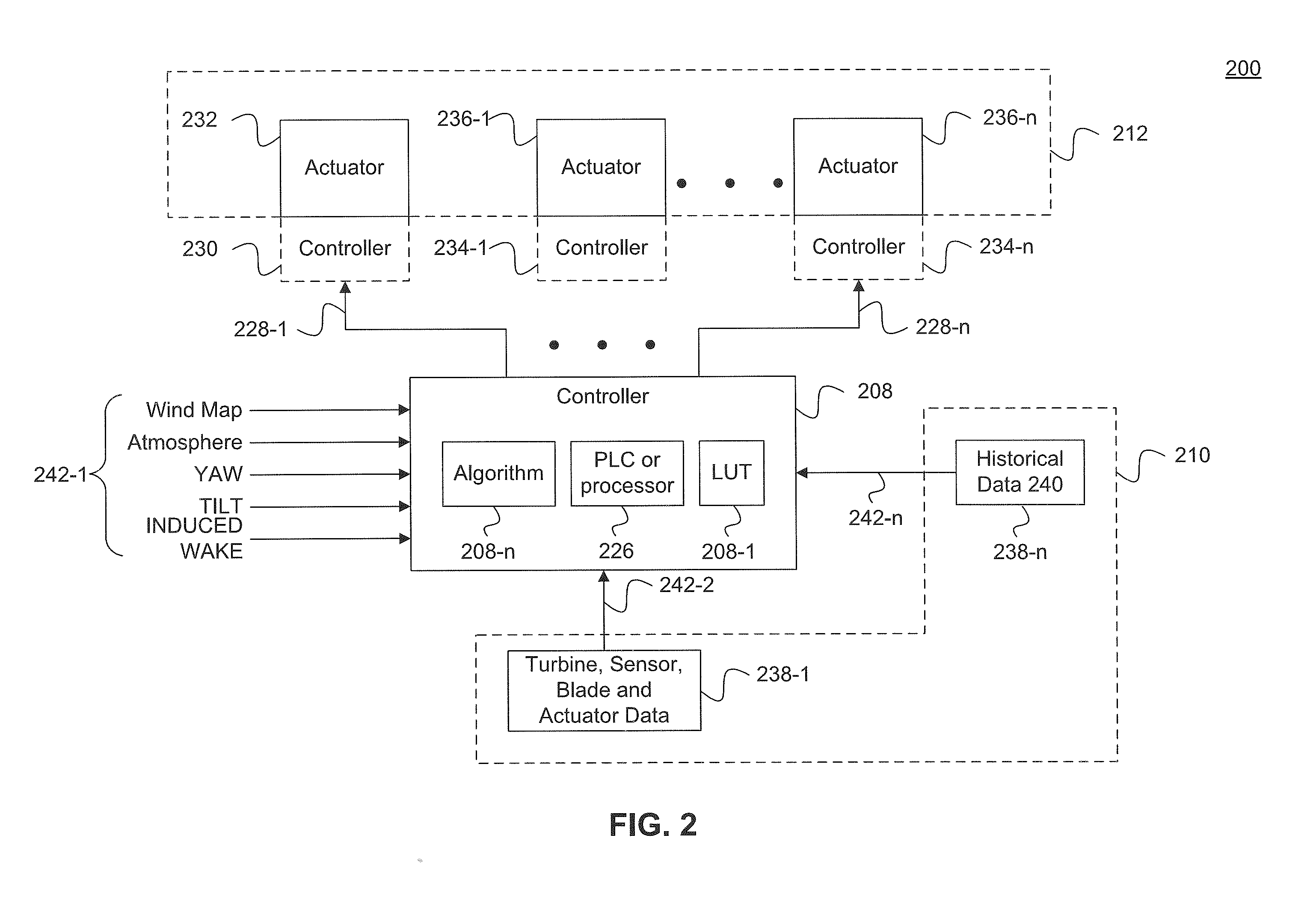
A system and method are provided to increase efficiency of turbines in wind farms. A sensor is configured to generate a wind map of an inflow of wind. A controller is configured to generate a control signal based the wind map. A pitch adjustment device configured to adjust pitch of a blade of the turbine based on the control signal.

Description

CROSS-REFERENCE TO RELATED APPLICATIONS[0001]This is application claims benefit under 35 U.S.C. 119(e) to U.S. Provisional Application No. 61 / 378,740, filed Aug. 31, 2010, which is incorporated by reference in this application in its entirety.BACKGROUND[0002]1. Field of the Invention[0003]The invention generally relates to pitch control of a blade that is part of a wind turbine system.[0004]2. Background Art[0005]Increasing predictability, efficiency and lifetime of wind turbines is essential to continued advancement of wind-based clean energy. One way to increase power generation predictability and efficiency, and turbine life, is through active, dynamic pitch control of blades of the turbine, such that the blades are configured or positioned to most efficiently and effectively travel through incoming wind. However, current turbines use either no pitch control, or at most use reactive pitch control. Both negatively effect efficiency and life of the turbines as the blades are not op...

Claims


Application Information

Patent Timeline
Patent Type & Authority Applications(United States)
IPC IPC(8): F01D7/00
CPCF03D7/0224F03D7/0232F03D7/042F05B2260/821F05B2260/8211F05B2270/1095Y02E10/723F05B2270/404F05B2270/602F05B2270/604F05B2270/605F05B2270/606F05B2270/80F05B2270/322Y02E10/72
Inventor ROGERS, PHILIP L.BELEN, JR., FREDERICK C.DAKIN, ELIZABETH A.MAMIDIPUDI, PRIYAVADAN
Owner BLUESCOUT TECH INC
Why Eureka
Try Eureka