Electrical connector

a technology of soldering tails and connectors, applied in the direction of coupling devices, electric discharge tubes, two-part coupling devices, etc., can solve the problems of not being able to quickly and accurately insert soldering tails in printed circuit boards, and achieve accurate and efficient assembly, strengthen soldering tails, and prevent soldering tail deformation or fracture

Inactive Publication Date: 2012-03-01
CHENG UEI PRECISION IND CO LTD
View PDF1 Cites 13 Cited by
  • Summary
  • Abstract
  • Description
  • Claims
  • Application Information

AI Technical Summary

Benefits of technology

[0006]As described above, the electrical connector of the present invention utilizes the lid to position the soldering tails of the terminals so as to strengthen the soldering tails and further prevent the soldering tails from deformation or fracture, when the soldering tails are inserted into a printed circuit board. So an accurate and efficient assembly can be achieved for the electrical connector and the printed circuit board.

Problems solved by technology

As a result, when the soldering tail is inserted into the printed circuit board, the soldering tail is apt to be curved or fractured that makes the soldering tail fail to be quickly and accurately inserted in the printed circuit board.

Method used


Image

  • Electrical connector
  • Electrical connector
  • Electrical connector

Examples


Embodiment Construction

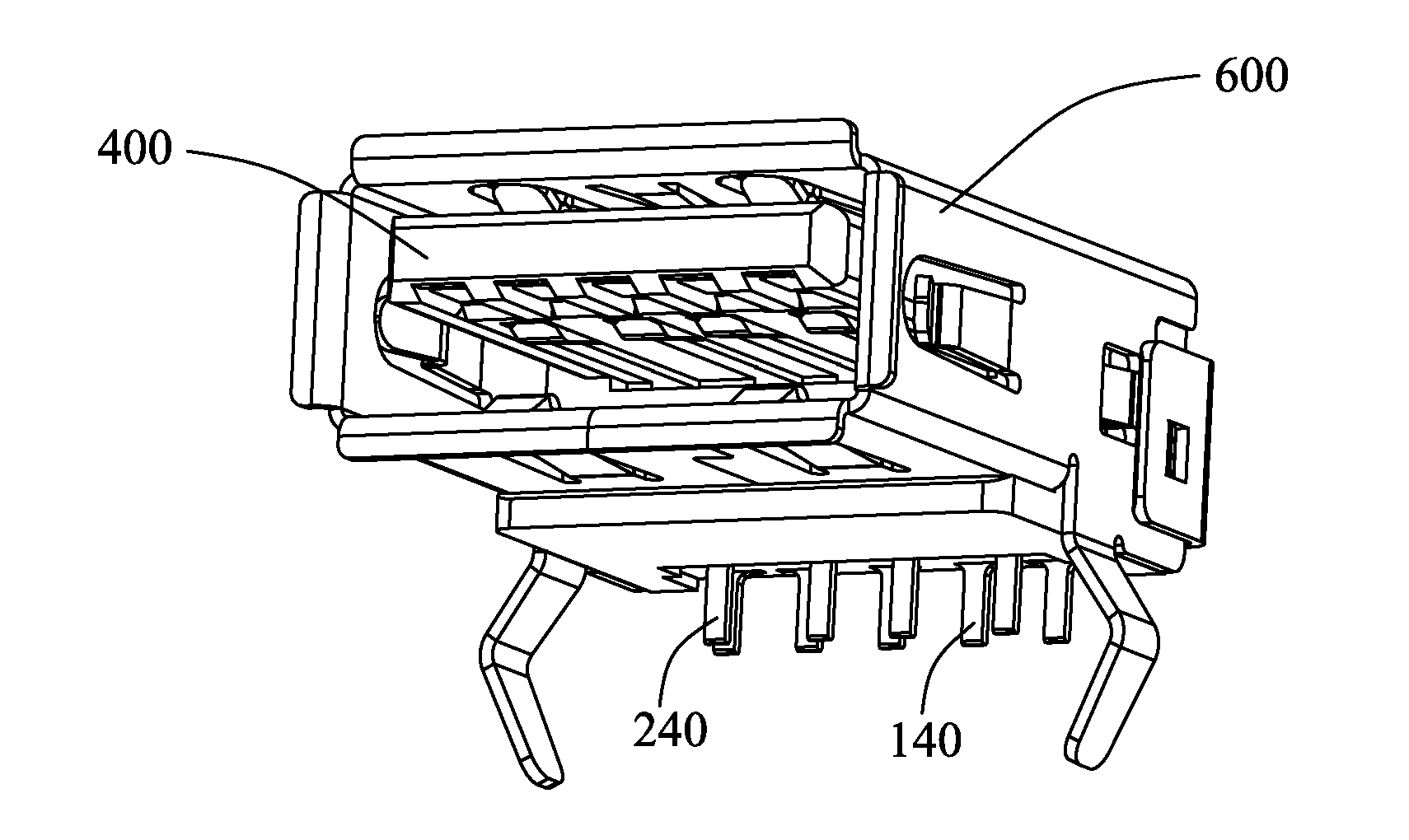
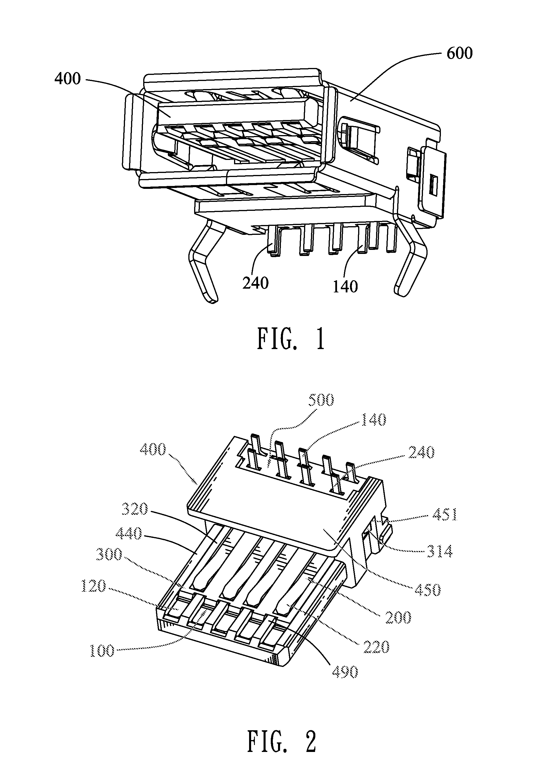
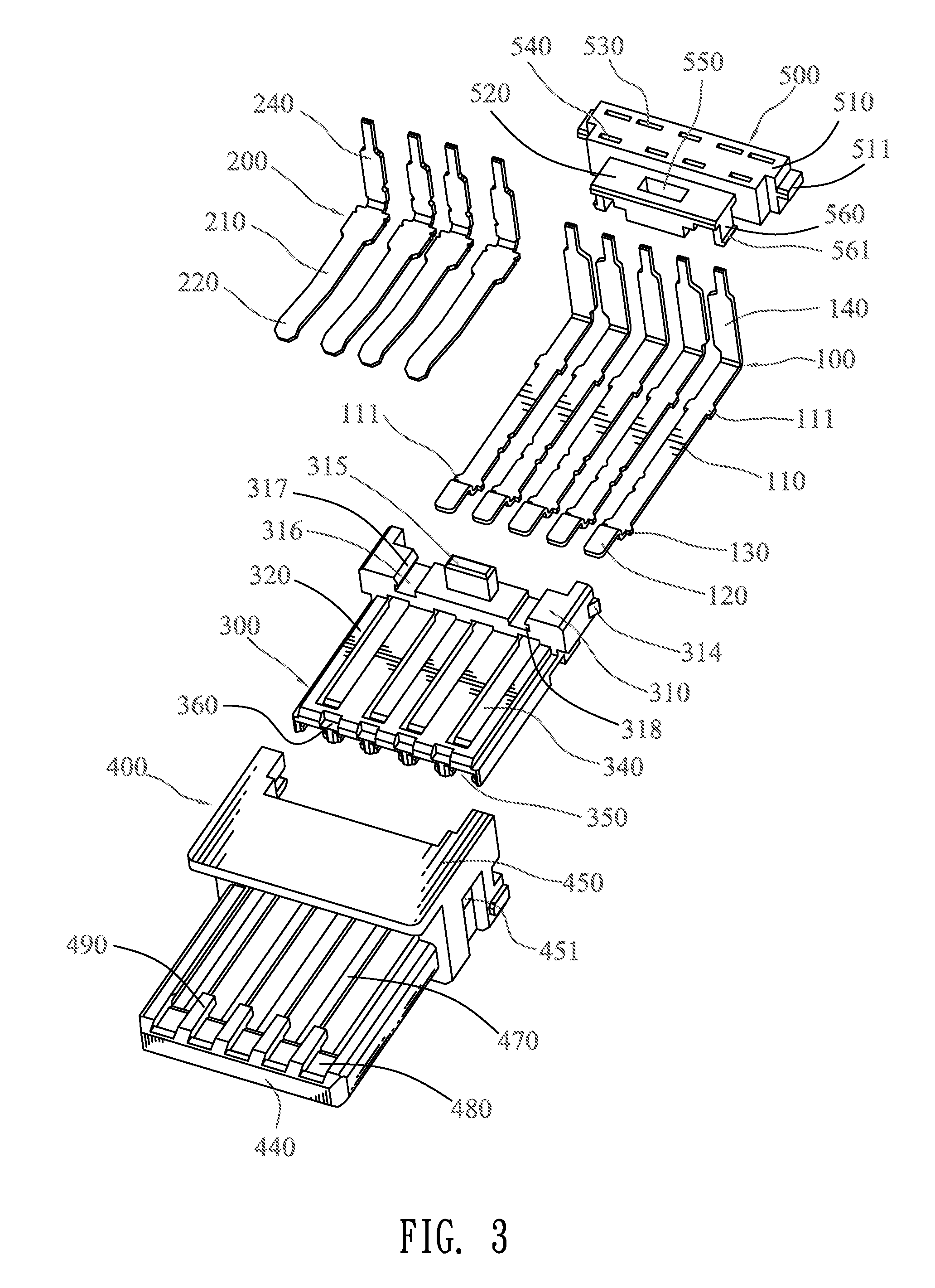
[0012]Referring to FIG. 1, FIG. 2 and FIG. 3, an electrical connector according to the present invention includes an insulating housing 400, an insulating body 300 mounted to the insulating housing 400, a plurality of first terminals 200 disposed in the insulating body 300, a plurality of second terminals 100 disposed in the insulating body 300 and propped by the insulating housing 400, a lid 500 mounted to a rear of the insulating body 300 for positioning and strengthening first and second soldering tails 240, 140 of the first terminals 200 and the second terminals 100, and a shielding shell 600 surrounding the insulating body 300, the insulating housing 400 and the lid 500.

[0013]Referring to FIGS. 3-5, the insulating housing 400 has a rectangular base body 450 and a tongue board 440 extending forward from a lower portion of a front of the base body 450. A top of the tongue board 440 defines a rectangular receiving recess 470 extending longitudinally to penetrate through the base b...


PUM


Abstract

An electrical connector includes an insulating body having a base portion and a tongue portion extending forward from the base portion, a plurality of terminals disposed in two opposite surfaces of the tongue portion and each having a soldering tail which stretches behind the base portion and further projects upward beyond a top of the base portion, and a lid having a positioning body and a fastening portion protruding forward from the positioning body. The positioning body defines a plurality of positioning apertures spaced from one another and each extending vertically to penetrate through the positioning body. The fastening portion is mounted to the top of the base portion to make the positioning body locate behind the base portion. The soldering tails are inserted in the positioning apertures to be positioned and strengthened by the positioning body, with free ends thereof projecting beyond a top of the positioning body.

Description

BACKGROUND OF THE INVENTION[0001]1. Field of the Invention[0002]The present invention relates to an electrical connector, and more particularly to an electrical connector capable of firmly positioning soldering tails of terminals.[0003]2. The Related Art[0004]A conventional electrical connector includes an insulating body and a plurality of terminals disposed in the insulating body. The insulating body has a base portion and a tongue portion extending forward from the base portion. The terminal has a fastening strip, a contact portion and a soldering tail connected with two opposite ends of the fastening strip. The soldering tail is perpendicular to the fastening strip and stretches behind the base portion of the insulating body, with a free end projecting beyond a top or bottom of the base portion for being inserted into a printed circuit board. However, the soldering tail is freely hanged in the air without being positioned by any positioning structure. As a result, when the solde...

Claims


Application Information

Patent Timeline
Patent Type & Authority Applications(United States)
IPC IPC(8): H01R24/00
CPCH01R12/724H01R12/707
Inventor WANG, YAO-TINGSU, YU-HUNG
Owner CHENG UEI PRECISION IND CO LTD
Why Eureka
Try Eureka