
Beam selection in a multiple beam antenna in a fixed wireless cpe

a fixed wireless cpe and antenna technology, applied in the direction of transmission monitoring, receiver monitoring, substation equipment, etc., can solve the problems of low data rate, high cpe installation cost, and failure of previous generations of fixed wireless services

Active Publication Date: 2012-03-01
VERIZON PATENT & LICENSING INC
View PDF3 Cites 100 Cited by
  • Summary
  • Abstract
  • Description
  • Claims
  • Application Information

AI Technical Summary

Problems solved by technology

However, previous generations of fixed wireless services have generally been unsuccessful.
Expensive network equipment and customer premises equipment (CPE), high CPE installation costs, use of proprietary technology, and low data rates are among some of the reasons these fixed wireless services remained unpopular.
However, CPE and installation costs have remained a barrier to successfully promoting bundled services over fixed wireless networks.

Method used


Image

  • Beam selection in a multiple beam antenna in a fixed wireless cpe
  • Beam selection in a multiple beam antenna in a fixed wireless cpe
  • Beam selection in a multiple beam antenna in a fixed wireless cpe

Examples


Embodiment Construction

[0013]The following detailed description refers to the accompanying drawings. The same reference numbers in different drawings identify the same or similar elements. Also, the following detailed description does not limit the invention.

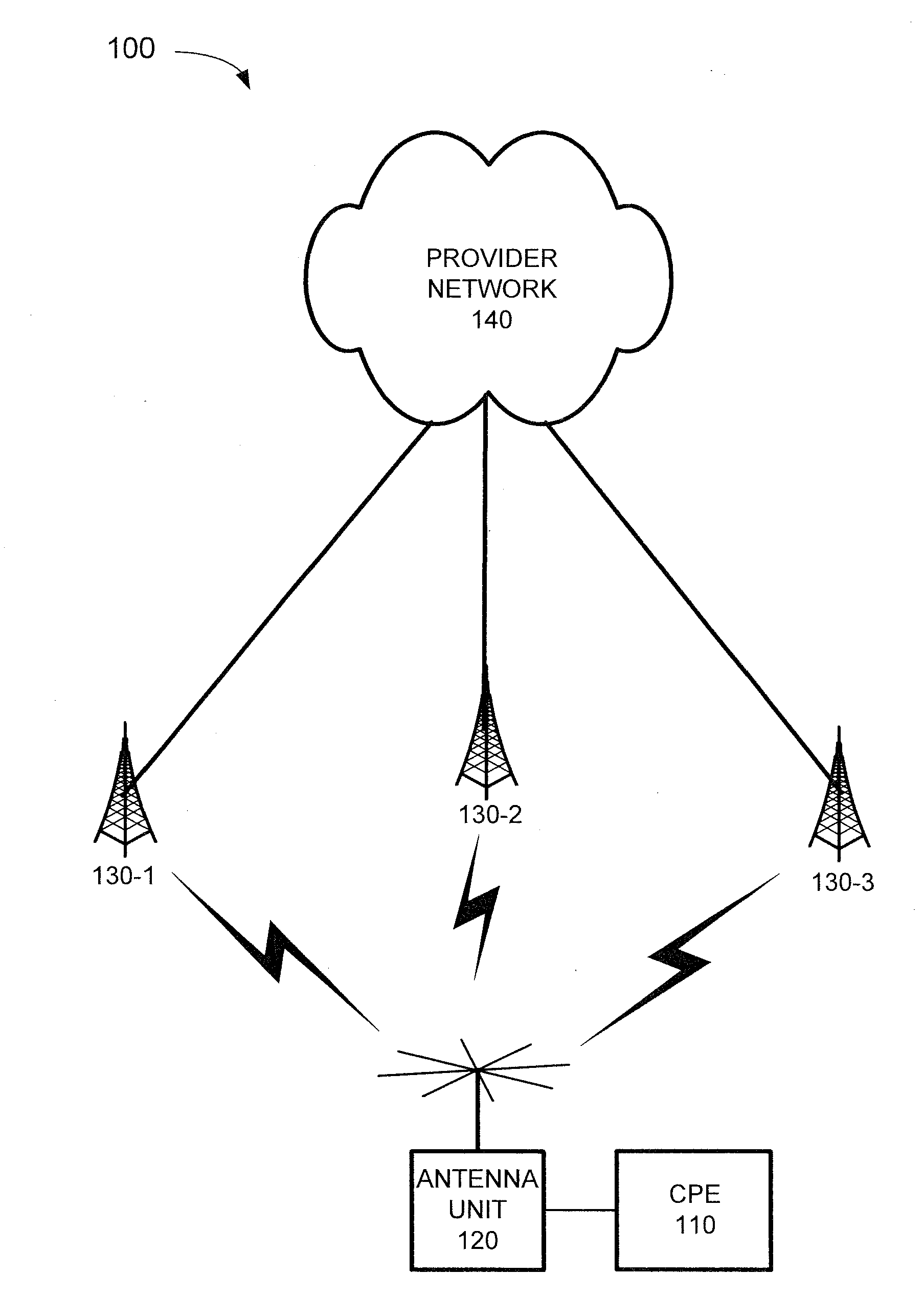
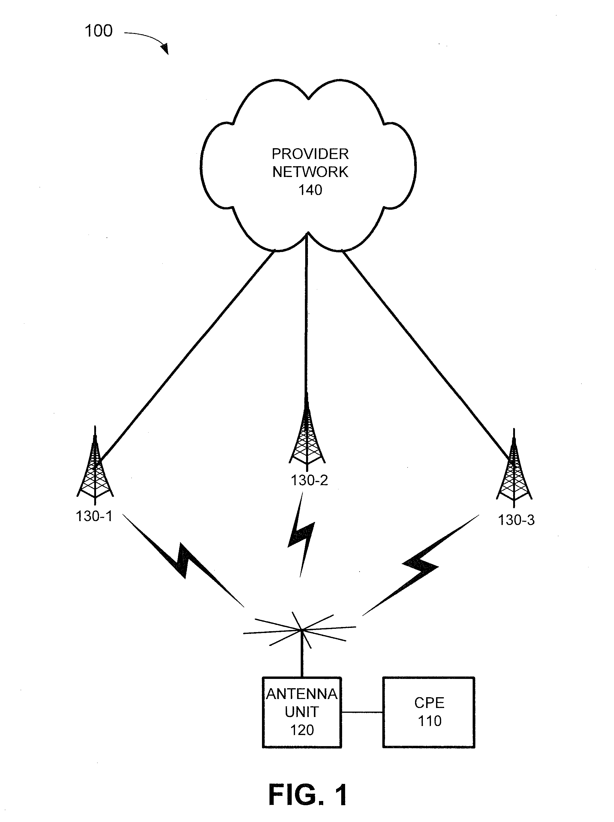
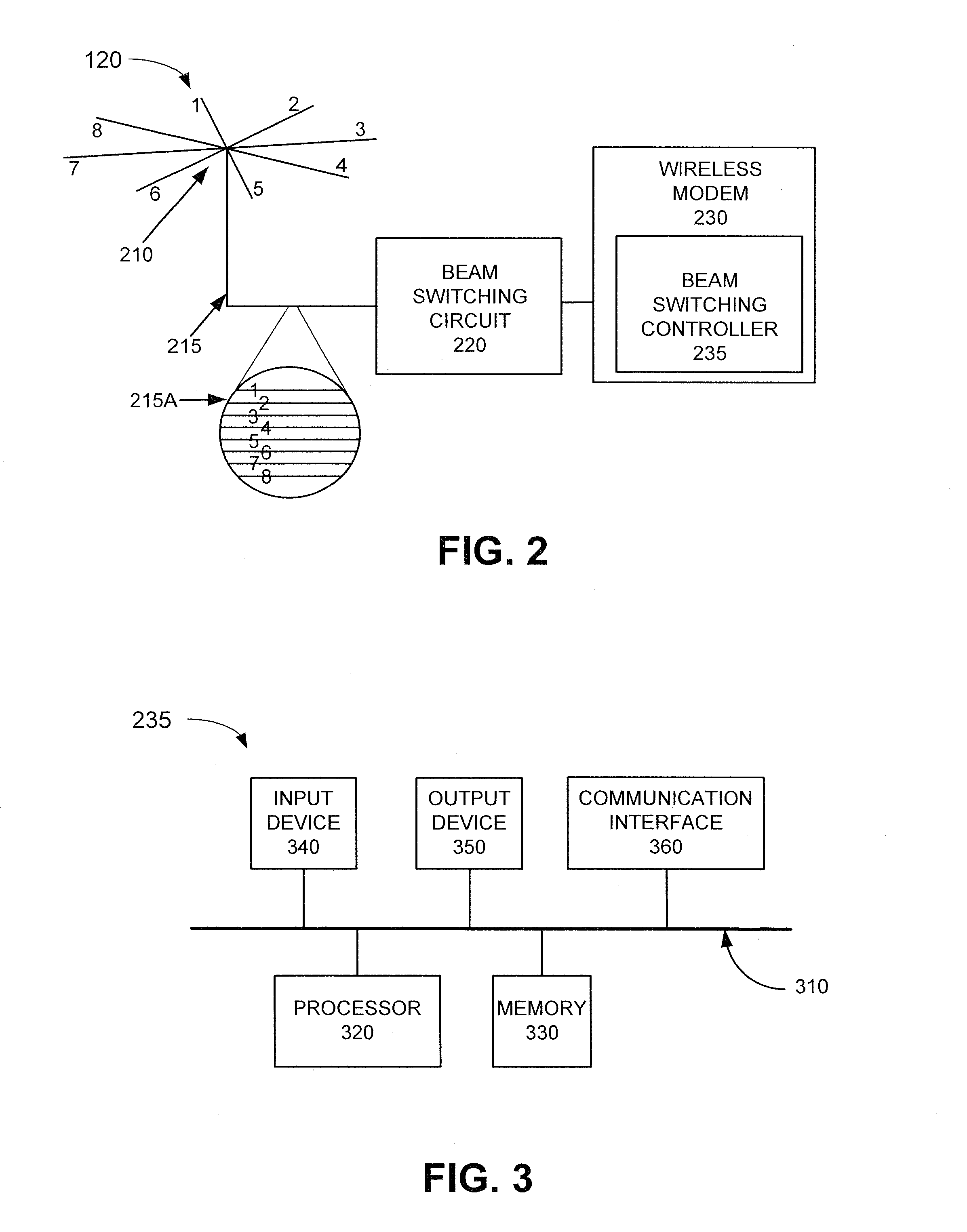
[0014]An implementation described herein may relate to aiding an operator to install an antenna unit with a multiple beam antenna in an acceptable location by determining whether one or more metrics associated with particular beams of the multiple beam antenna satisfy one or more thresholds. The antenna unit may include one or more indicators for informing the operator whether the unit is in an acceptable location. For example, the antenna unit may activate a first indicator if one or more metrics associated with particular beams of the multiple beam antenna are greater than a first set of thresholds, may activate a second indicator if the one or more metrics are not greater than the first set of thresholds but are greater than a second set of thresho...


PUM


Abstract

A method includes scanning beams of a multiple beam antenna to collect metrics associated with the beams; selecting a best beam based on the collected metrics or based on a manual selection received from an operator; retrieving thresholds associated with the metrics; comparing the collected metrics, associated with the selected best beam, to the retrieved thresholds; and determining whether the antenna unit is in an acceptable location based on the comparison. Another method includes scanning beams of the multiple beam antenna to collect metrics associated with the beams; selecting a best beam based on the collected metrics; determining a serving beam; comparing a set of metrics associated with the selected best beam with a corresponding set of metrics associated with the serving beam; and determining whether to switch from the serving beam to the selected best beam based on the comparison.

Description

BACKGROUND INFORMATION[0001]Bundled media services (e.g., combination packages of television, telephone, and broadband Internet services) have been successfully offered to households with wired connections to service provider networks. Households in areas without such wired connections (e.g., customer in regions that cannot be reached via conventional communication media, such as optical cables, copper cables, and / or other fixed wire-based technologies) may rely on fixed wireless services for some of these services (e.g., broadband access). However, previous generations of fixed wireless services have generally been unsuccessful. Expensive network equipment and customer premises equipment (CPE), high CPE installation costs, use of proprietary technology, and low data rates are among some of the reasons these fixed wireless services remained unpopular.[0002]As wireless network data rates improve using fourth generation (4G) technologies, such as Long-Term Evolution (LTE), such techno...

Claims


Application Information

Patent Timeline
IPC IPC(8): H04B17/00
CPCH04B7/0408H04B17/27H04B17/104
Inventor KAMEL, RAAFAT EDWARDKAMDAR, KAMLESHAGUIRRE, SERGIO
Owner VERIZON PATENT & LICENSING INC
Learn More