

Phase sensing and scanning time of flight LADAR using atmospheric absorption bands
a technology of phase sensing and scanning time, applied in the field of electronic imaging systems, can solve the problems of severe deformation of the performance of this and other staring and scanning ladar systems in outdoor operation, unavoidable reception of solar background ir, and degrade the signal-to-noise ratio of the system
Active Publication Date: 2012-10-02
PFG IP +1
View PDF11 Cites 84 Cited by
- Summary
- Abstract
- Description
- Claims
- Application Information
AI Technical Summary
Benefits of technology
"The patent describes a method and device for using a special laser to detect objects. The laser is tuned to a specific wavelength and emits a beam of light that is absorbed by the atmosphere. When the beam is reflected from an object, it is modulated at a specific frequency and the phase of the reflected beam is compared to the transmitted beam to determine the distance of the object. The method can be used in a scanning device to measure the range of objects at different locations on the surface. The technical effect of this invention is to provide a more accurate and efficient way to measure distances of objects using a laser."
Problems solved by technology
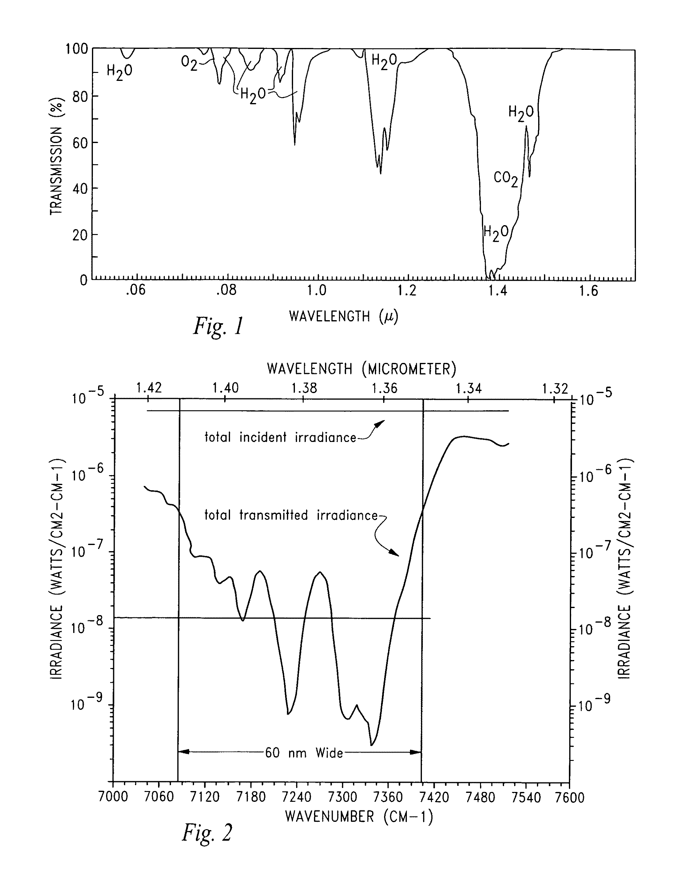
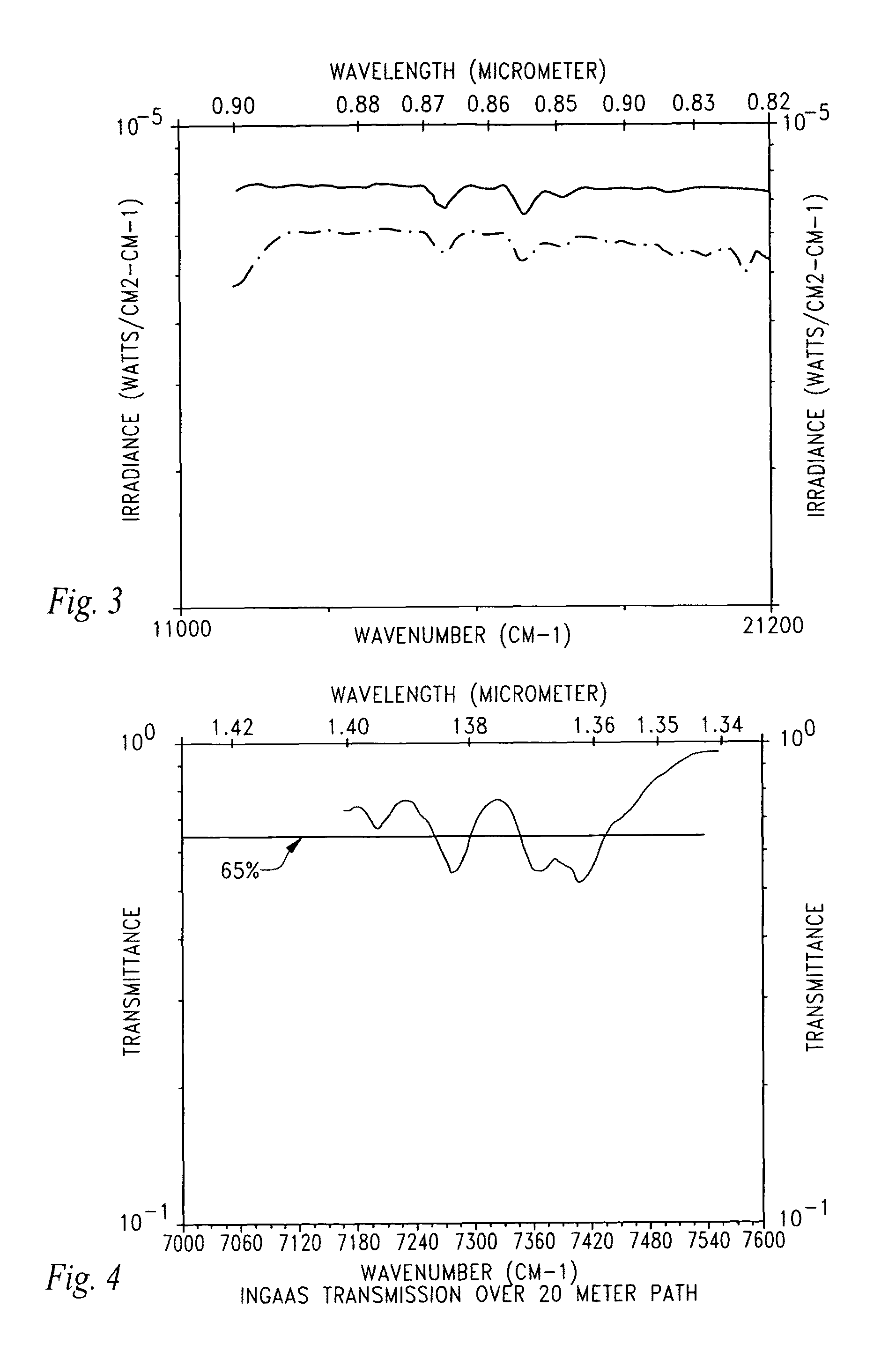
Unfortunately, the performance of this and other staring and scanning LADAR systems is severely degraded in operation outdoors, due in significant part to high solar background infrared radiation (IR) at ground level which is the result of the solar radiation spectrum incident upon the surface of the Earth.
The high solar background IR is unavoidably received in outdoor operation and not only degrades the signal-to-noise ratio of the system, but also severely degrades the system's modulation contrast.
By illuminating the scene with 850-nm laser energy, the prior art systems are undesirably bounded by two issues: 1) the system cannot increase the transmission power without becoming non-eye safe, and, 2) the system cannot reduce the received background IR energy by narrowing the receiver spectral filter significantly without having to compensate for laser line drift due to temperature variations or for spectral filter bandpass drift due to various illumination incident angles.
Method used
View moreImage
Smart ImageViewing Examples

Examples
second embodiment
[0077]In FIG. 10b, the transimpedance amplifier's integration capacitor continually integrates over the frame and the results are sampled and held at various time periods. The sampling of the sample and hold capacitor can be performed randomly and the sine wave can be reconstructed in suitable processing electronics such as an FPGA.
third embodiment
[0078]In FIG. 10c, an in-circuit mixer is used to determine the phase of the return signal. The output of the mixer is a DC value that is proportional to the phase delay between the received signal and the original diode modulation drive signal. A mixing circuit desirably has very high gain and can be very selective in its amplification.
Login to View More PUM
 Abstract
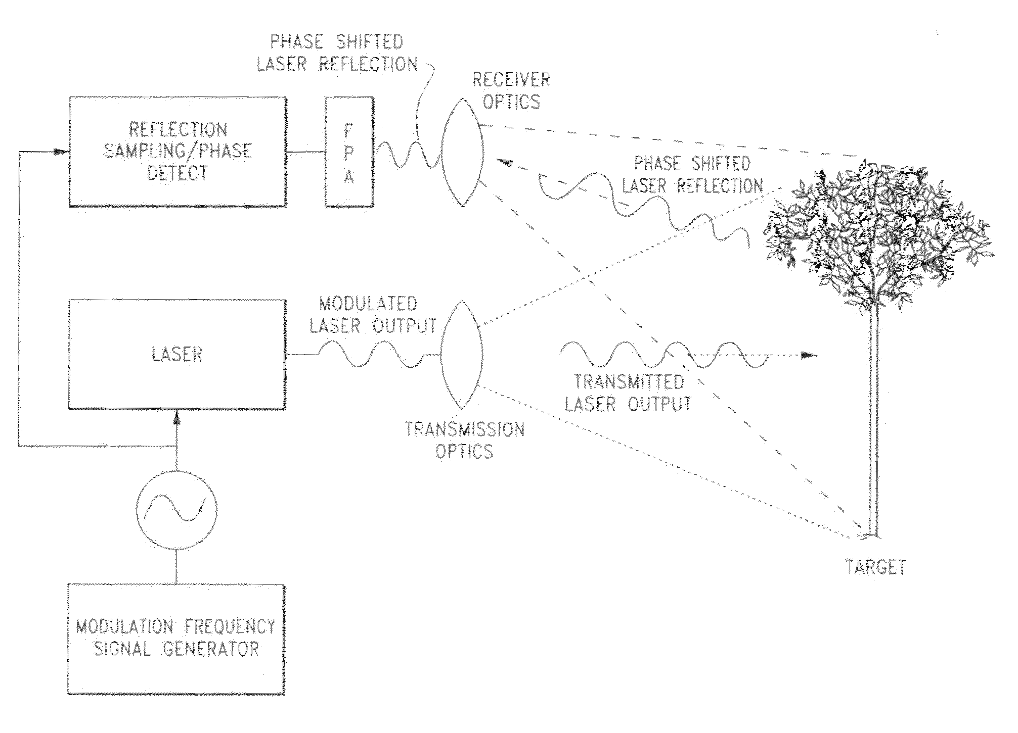
A phase-sensing and scanning time-of-flight LADAR method and device are disclosed that take advantage of an atmospheric absorption bands within the solar IR spectrum.In the phase-sensing LADAR embodiment, an object is illuminated with electromagnetic energy such as a laser beam having a wavelength substantially equal to a predetermined atmospheric absorption band such as 1.39 microns. The transmitted laser beam is modulated at a predetermined frequency and has a first phase. The phase of the reflected and returned laser beam is altered proportional to the distance of the object and has a second phase. The first phase of the transmitted signal and the second phase of the received signal are compared and used to determine the distance of the object from the device. The system may comprise a modified laser that is tuned to operate in an atmospheric absorption band. A method to identify range ambiguity is disclosed by periodically altering the modulation frequency from a first modulation frequency to a second modulation frequency.In the scanning LADAR embodiment, an object is scanned or illuminated with electromagnetic energy having a wavelength substantially equal to a predetermined atmospheric absorption band at a first time and detects the reflection of the beam at a second time. The difference in time from the transmission of the scanning beam and the detection of the reflection of the beam from the object is used to calculate the range of the object.
Description
CROSS-REFERENCE TO RELATED APPLICATIONS[0001]This application claims the benefit of U.S. Provisional Patent Application No. 61 / 273,577, filed on Aug. 6, 2009, entitled “Scannerless LADAR Receiver” pursuant to 35 USC 119, which application is incorporated fully herein by reference.STATEMENT REGARDING FEDERALLY SPONSORED RESEARCH AND DEVELOPMENT[0002]N / AFIELD OF THE INVENTION[0003]The invention generally relates to the field of electronic imaging systems. More specifically, the invention relates to a phase sensing or scanning time-of-flight LADAR system operating in an atmospheric IR absorption band.BACKGROUND OF THE INVENTION[0004]As devices such as robotic vehicles get smaller (i.e., iRobot®'s Packbot®) in settings where autonomous navigation requirements are lessened, the operational requirements for ranging sensors such as LADAR sensing systems are reduced but not all together eliminated. In these and other applications, fewer LADAR sensors per vehicle are required but such sensor...
Claims
Login to View More Application Information
Patent Timeline
 Patent Type & AuthorityPatents(United States)
IPC IPC(8): G01C3/08
CPCG01S17/36G01S17/89G01S17/894
InventorLUDWIG, DAVIDAZZAZY, MEDHAT
OwnerPFG IP