Multiple station vacuum deposition apparatus for texturing a substrate using a scanning beam

a vacuum deposition and scanning beam technology, applied in vacuum evaporation coatings, electrolysis components, coatings, etc., can solve the problems of sputtering machines, laser texturing machines may constitute a significant portion of the overall cost of manufacturing disks, and severely limited throughput,

Inactive Publication Date: 2001-03-13
WESTERN DIGITAL TECH INC
View PDF10 Cites 80 Cited by
  • Summary
  • Abstract
  • Description
  • Claims
  • Application Information

AI Technical Summary

Problems solved by technology

The overall cost and performance of a contemporary fixed-disk disk drive, such as a magnetic hard disk drive, depend significantly on the cost and performance of each magnetic disk within the drive.
The cost of manufacturing magnetic disks depends in part on the cost and efficiency of operation of various machines used to carry out numerous processes involved in manufacturing the disks.
The standalone machine typically laser textures one substrate at a time and its throughput may be severely limited by factors such as the substrate handling time.
Also, the cost of the laser texturing machine may constitute a significant portion of the overall cost of manufacturing the disks.
The cost of a sputtering machine adds a significant portion to the overall cost of manufacturing the disks.
Texturing of the landing zone reduces the effective contact area between the slider and the surface of the landing zone thereby reducing the static friction forces ("stiction") that must be overcome to separate the slider from the surface of the landing zone when the disk drive is powered on.

Method used


Image

  • Multiple station vacuum deposition apparatus for texturing a substrate using a scanning beam
  • Multiple station vacuum deposition apparatus for texturing a substrate using a scanning beam
  • Multiple station vacuum deposition apparatus for texturing a substrate using a scanning beam

Examples


Embodiment Construction

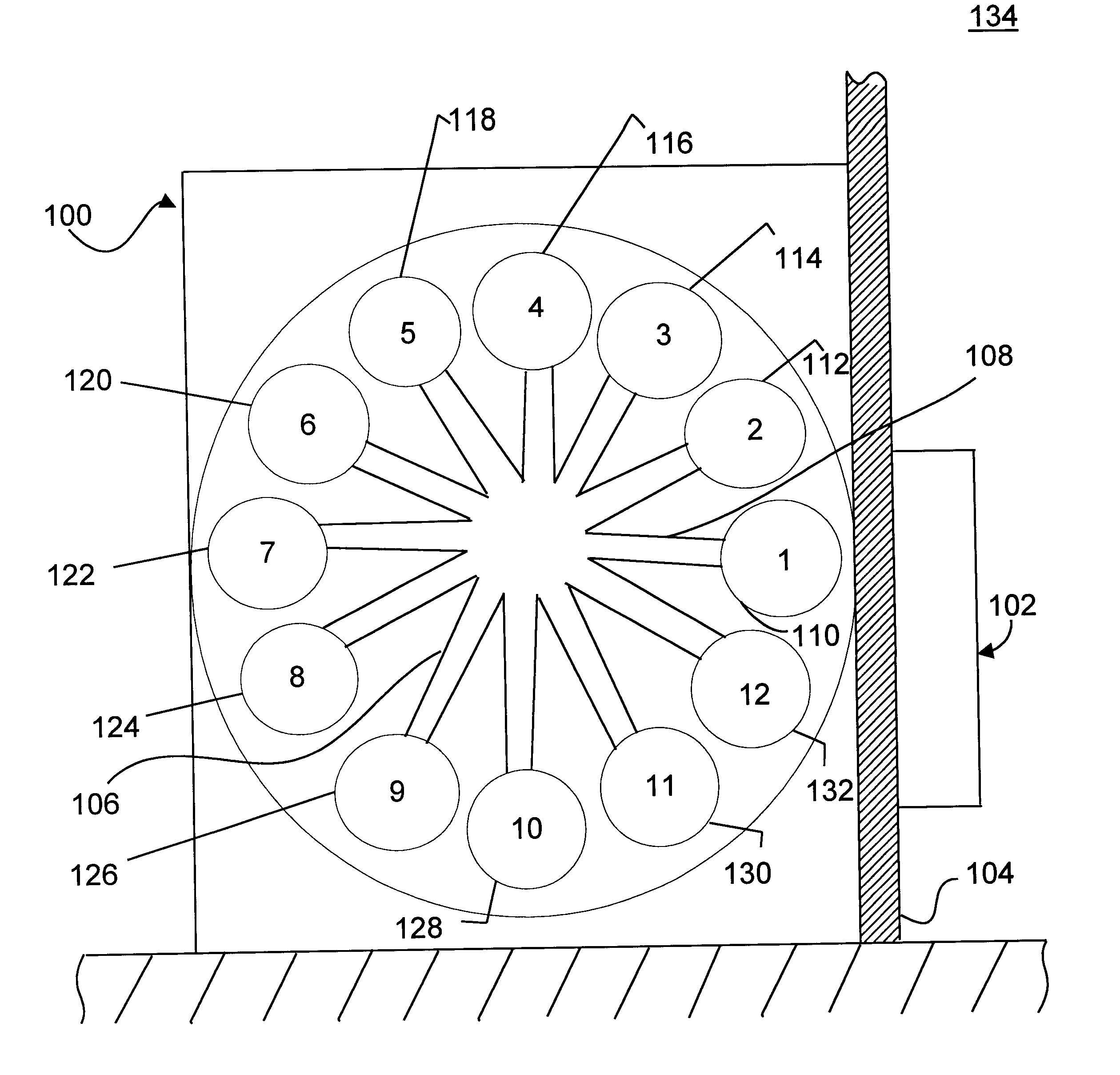
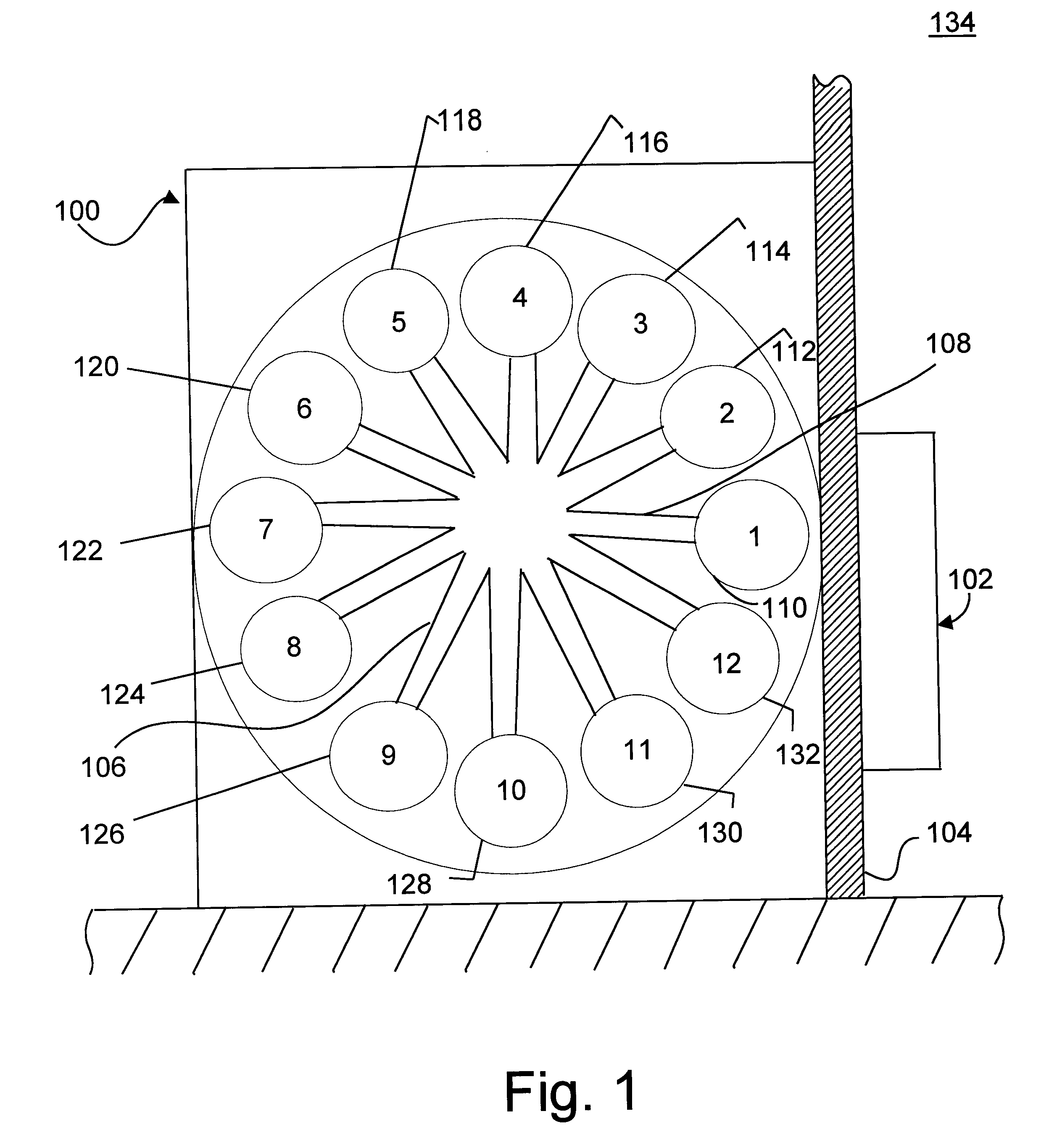
With reference to FIG. 1, a machine 100, referred to herein interchangeably as either a stationary vacuum deposition machine or a stationary sputtering machine, includes a robot 102, a series of stations 110 to 132, and a transport means such as a centrically beared wheel 106. Wheel 106 includes radially disposed grippers such as gripper 108, a portion of which is shown in FIG. 1. A wall 104 separates series of stations 110 to 132 from a cleanroom 134.

In operation, cassettes (not shown) of substrates made from metal, glass, or ceramic are positioned in front of robot 102 in cleanroom 134; an example of a metal substrate is an aluminum substrate which is typically plated with a layer of nickel-phosphorous. Robotic arms (not shown) within robot 102 load each substrate in sequence, one at a time, from a cassette into an entrance station 110. From entrance station 110, each substrate is transported by wheel 106 in a pipeline process to each station for per stage processing.

Wheel 106 is ...


PUM

PropertyMeasurementUnit
timeaaaaaaaaaa
focal lengthaaaaaaaaaa
distanceaaaaaaaaaa

Abstract

A stationary vacuum deposition machine for use in a method for processing substrates to make magnetic hard disks includes a series of stations and a transport. The series of stations includes an entrance station for receiving substrates into the machine and a predetermined station. The transport operates in a cycle with each cycle including a transport phase and a stationary phase. The transport causes all the substrates that are in the machine to be moved during the transport phase, and be temporarily held stationary during the stationary phase, such that during each stationary phase a predetermined one of the stations is occupied by one of the substrates while each of a plurality of others of the stations is occupied by a respective one of a plurality of others of the substrates. The machine further includes a plurality of vacuum deposition stations and a scanning beam generator. Each vacuum deposition station operates during each stationary phase such that each station causes a thin film to be deposited on a respective one of the substrates. The scanning beam generator directs a scanning beam at the substrate occupying the predetermined station while the substrate is held stationary to produce a textured pattern.

Description

1. Field of the InventionThis invention relates to processing of a substrate in making a disk to be used in a fixed-disk disk drive. More particularly, it relates to using a vacuum deposition machine to laser texture an inner annular region or landing zone of a substrate.2. Description of the Prior Art and Related InformationThe overall cost and performance of a contemporary fixed-disk disk drive, such as a magnetic hard disk drive, depend significantly on the cost and performance of each magnetic disk within the drive.The cost of manufacturing magnetic disks depends in part on the cost and efficiency of operation of various machines used to carry out numerous processes involved in manufacturing the disks. These processes include texturing processes. Typically, one machine is used for "full-surface" texturing and another machine is used for landing zone texturing. An example of a machine for landing zone texturing is a standalone laser texturing machine which includes a rotating and...

Claims


Application Information

Patent Timeline
Patent Type & Authority Patents(United States)
IPC IPC(8): C23C14/56C23C14/34G11B5/84G11B5/851G11B5/82
CPCC23C14/3464C23C14/568G11B5/851G11B5/82
Inventor GORNICKI, STELLA ZOFIAKRAJNOVICH, DOUGLAS J.
Owner WESTERN DIGITAL TECH INC
Why Eureka
Try Eureka