2-D Planar VCSEL Source for 3-D Imaging

a 3-d imaging and vcsel source technology, applied in the field of 3d optical sensing and imaging apparatus, can solve the problems of detectors and complex processors limiting applications to limited environments, and limiting applications to a few areas, so as to achieve more accurate proximity sensing

Active Publication Date: 2015-12-17
PRINCETON OPTRONICS
View PDF2 Cites 80 Cited by
  • Summary
  • Abstract
  • Description
  • Claims
  • Application Information

AI Technical Summary

Benefits of technology

[0019]In a variant embodiment reflected radiation is detected using a photodetector array substantially matched with the VCSEL array to provide a structured time synchronized illumination and detection means to measure a time of flight and intensity of the reflected radiation for more accurate proximity sensing, imaging and scanning applications.

Problems solved by technology

Current proximity sensing imaging and scanning apparatus requiring sophisticated and complex optical sources, detectors and complex processors limit applications to just a few areas due to cost consideration.
One major requirement in this technique is that the distance between the two cameras have to be carefully calibrated using a complex procedure which limits the application to limited environment.
While the image resolution is quite high, it is only possible by using a customized superconducting narrow wire single-photon detector.
Clearly, such sophisticated apparatus and technique is well out of the realm of everyday applications.
Differences in reflectance and even shapes of objects tend to change the detected light resulting in errors in distance measurement.
The sources currently available have for a reasonable cost have low intensity and / or are highly divergent which limits the distance that can be accurately measured as the reflected intensity becomes lower than the detection limit of the detector or is similar to ambient light levels.
One drawback of a hybrid method is that each method requires an optical source that is specialized for that particular method and is therefore impractical to implement.
It is disclosed that when a transistor for each VCSEL is integrated with the laser array chip, matrix addressing of the array is feasible, except it becomes impractical for very large arrays.
The apparatus and method described therein is not particularly suited for simple applications mentioned earlier, or at a lower cost to expand usage to application other than gaming.

Method used


Image

  • 2-D Planar VCSEL Source for 3-D Imaging
  • 2-D Planar VCSEL Source for 3-D Imaging
  • 2-D Planar VCSEL Source for 3-D Imaging

Examples


Embodiment Construction

[0037]A broad framework and main principles and important aspects of the invention are disclosed using exemplary embodiments that are represented in different drawing figures. For clarity and ease of description, each embodiment includes only a few aspects. However, different aspects presented in each embodiment may be practiced separately or in various combinations and sub-combinations. Many different combinations and sub-combinations of the representative embodiments within the broad framework presented in this written specification, may be apparent to those skilled in the art but not explicitly shown or described, should not be construed as precluded.

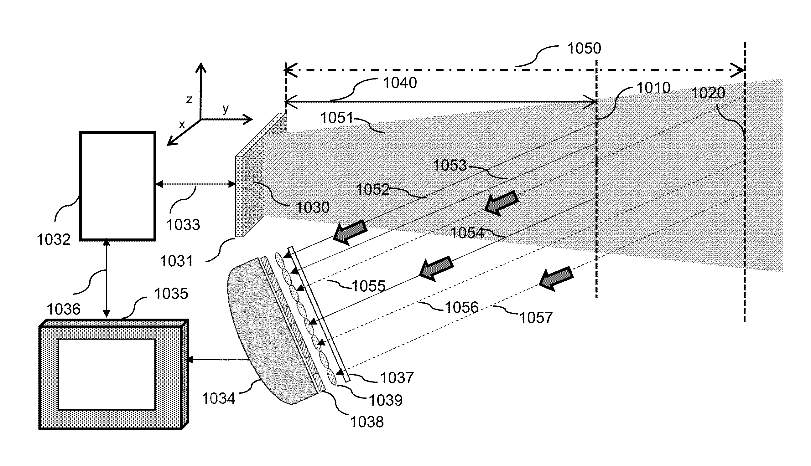
[0038]Vertical Cavity Surface Emitting Laser (VCSEL) emits radiation in a direction perpendicular to the substrate plane. The radiation emitted from a VCSEL is a substantially symmetric circular beam having a very low divergence (narrow beam emission). It is particularly suited for applying simple beam shaping elements such as variou...


PUM


Abstract

An apparatus and a method are provided for 3-D imaging and scanning using a 2-D planar VCSELs source configured as a lightfiled optical source. VCSELs are configured in different 2-D spatial arrangements including single VCSEL, or preferably a group, cluster, or array each to be operated effectively as an independent VCSEL array source. A set of microlens and an imaging lens positioned at a pre-determined distance collimates radiation from each VCSEL array source to a set of parallel beams. The parallel beams from different VCSEL array sources generated in a rapid pre-determined timing sequence provide scanning beams to illuminate an object. The radiation reflected from the object is analyzed for arrival time, pulse shape, and intensity to determine a comprehensive set of distance and intensity profile of the object to compute a 3-D image.

Description

CROSS REFERENCE TO RELATED APPLICATION[0001]This application is a Continuation-In-Part of the U.S. patent application Ser. No. 14 / 303,161 filed on Jun. 12, 2014 which claims priority benefit from the U.S. Provisional Patent Application No. 61 / 845,572 filed on Jul. 12, 2013, the contents of above mentioned applications are being incorporated by reference in their entirety.BACKGROUND OF THE INVENTION[0002]1. Field of the Invention[0003]The present invention relates to a 3-D optical sensing and imaging apparatus using an optical illumination source comprising Vertical Cavity Surface Emitting Lasers (VCSEL), and in particular, a lightfield optical source including 2-D planar array of VCSELs.[0004]2. Related Background Art[0005]There are many applications such as military and civilian surveillance, security and monitoring equipment, medical imaging, biometric imaging, gesture recognition input devices for interactive video games, motion activated input devices, automotive safety devices,...

Claims


Application Information

Patent Timeline
Patent Type & Authority Applications(United States)
IPC IPC(8): G01S7/481G01S17/02H01S5/022H01S5/42H01S5/00G01S17/89G01S7/484G01S7/4865G01S17/04G01S17/10G01S17/894
CPCG01S7/4815G01S17/89G01S17/026H01S5/02248H01S5/423H01S5/005G01S7/484G01S7/4816G01S17/10G01S7/4865G01S17/894G01S17/04H01S5/02325
Inventor GHOSH, CHUNI LALSEURIN, JEAN FRANCOISWATKINS, LAURENCE S.
Owner PRINCETON OPTRONICS
Why Eureka
Try Eureka