Configuration memory for a scanning beam device

a configuration memory and scanning beam technology, applied in the field of scanning beam devices, can solve the problems of reducing the size of scanning beam systems, and combining high resolution (>400,000 pixels) and wide fov (>30 degrees) in a single display or camera,

Active Publication Date: 2006-04-06
UNIV OF WASHINGTON
View PDF56 Cites 81 Cited by
  • Summary
  • Abstract
  • Description
  • Claims
  • Application Information

AI Technical Summary

Benefits of technology

[0012] The present invention relates generally to scanning beam systems and scanning beam devices which incorporate a memory structure (such as a non-volatile memory) for providing parametric data of the scanning beam device to a controller of a base station. The memory may provide an identification of the device and/or parametric data that allows the controller to conf

Problems solved by technology

Scanning beam systems fill the need, but the lack of low cost micro-optical systems with a wide field of view (FOV) have been the most significant barrier for reducing the size of scanning beam systems for use in minimally invasive medical imaging (flexible endoscopes), surveillance, industrial inspection and repair, machine and robotic vision systems, and micro-barcode scanners.
Combining both high resolution (>400,000 pixels) and wide FOV (>30 degrees) in a single display or camera is a difficult technical challenge.
The faster the mirror scans, the greater the forces acting on the mirror, which deforms the mirror surface, degrading image quality.
This limitation is especially true for the small, low cost resonant mirror scanners.
Rotating polygon mirror scanners can overcome this limitation or tradeoff between scan frequency and amplitude, except they are usually bulky, and costly.
However, at sVGA resolution and scan

Method used


Image

  • Configuration memory for a scanning beam device
  • Configuration memory for a scanning beam device
  • Configuration memory for a scanning beam device

Examples


Embodiment Construction

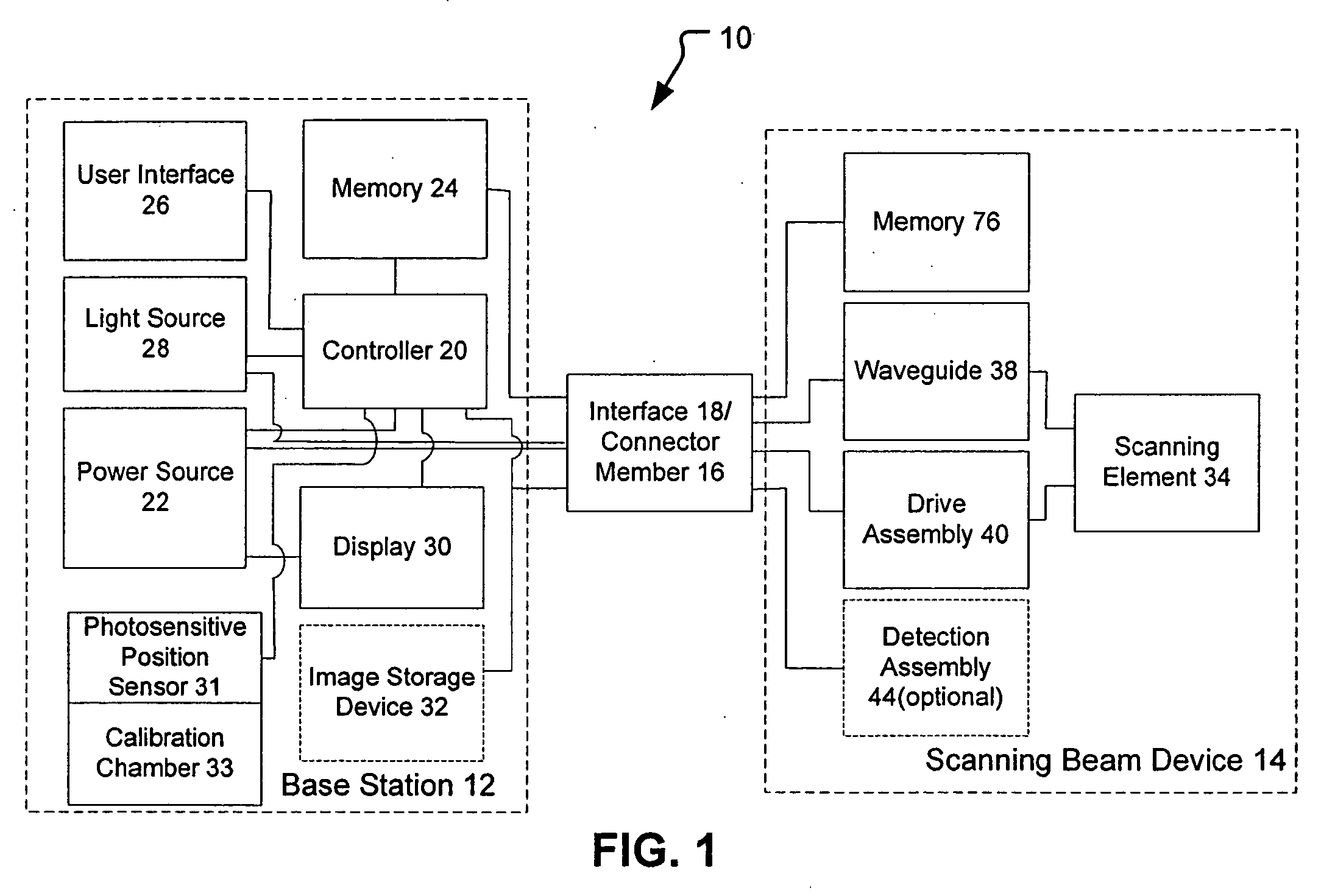
[0035] The scanning beam systems of the present invention will generally include a scanning beam device and a base station for controlling the scanning beam device. The scanning beam devices of the present invention may take on a variety of forms, but are typically in the form of a rigid or flexible endoscope, catheter, fiberscope, microscope, boroscope, bar code reader, an image display, or other device for generating images or acquiring images of a target area. The scanning beam devices of the present invention may be a limited use device (e.g., disposable device) or a multiple-use device. If the device is for medical use, the scanning beam devices will generally be sterile, either being sterilizable or being provided in hermetically sealed package for use.

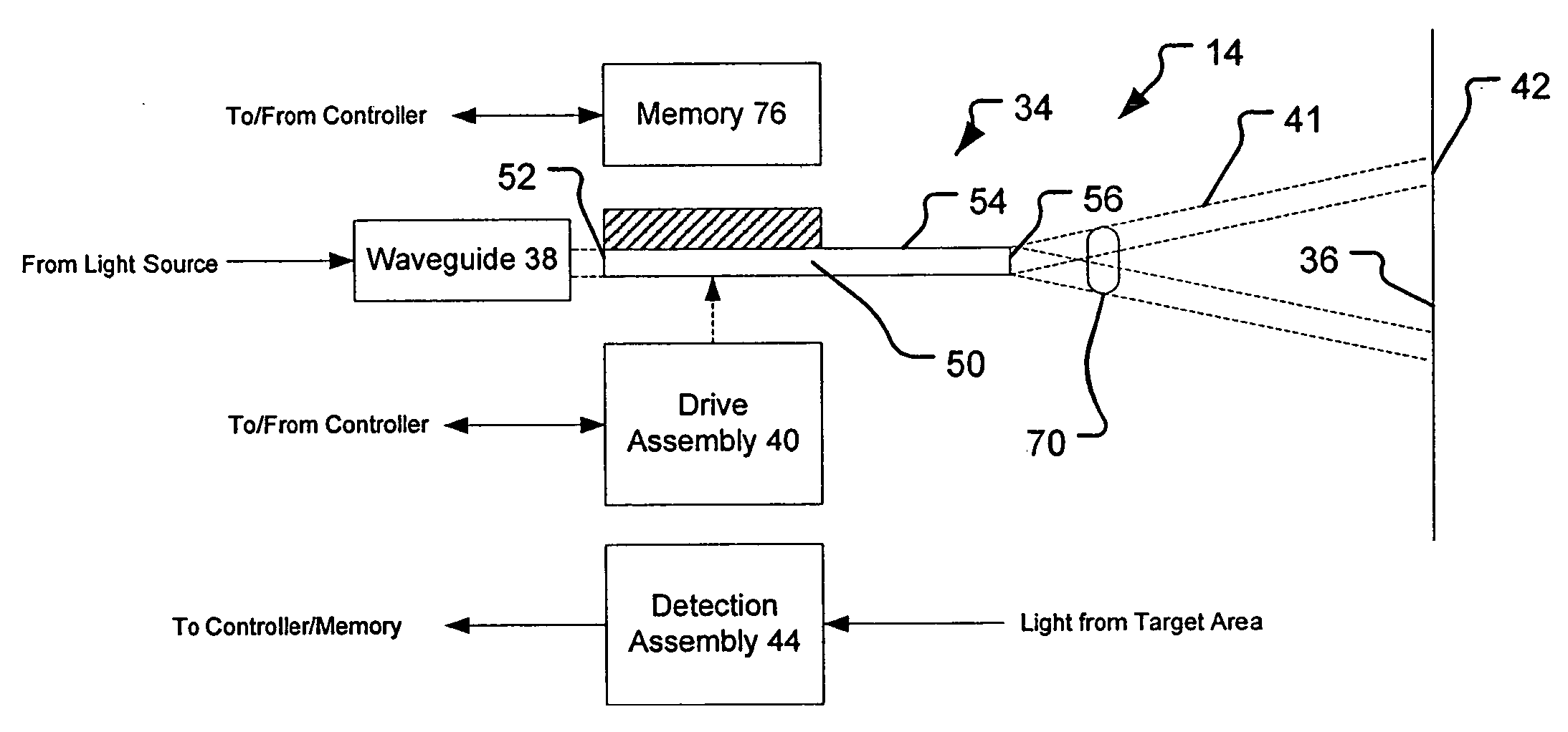
[0036] The scanning beam devices of the present invention include a scanning element for scanning a beam of light onto a target area. The scanning element preferably comprises a single, cantilevered optical fiber, but in other ...


PUM


Abstract

The present invention provides a memory element for providing compatibility information and/or parametric data about a scanning beam device to a universal base station. The present invention provides a memory coupled to the scanning beam device that provides parametric data, such as an identifier code, compatibility information, and other characteristics of the scanning beam device that is coupled to the universal base station. A controller of the base station may use the parametric data to configure or generate a control routine so as to allow the base station to properly operate the device.

Description

BACKGROUND OF THE INVENTION [0001] The present invention relates generally to scanning beam devices. More specifically, the present invention relates to scanning fiber devices that have a memory element which includes data that improves operation of the scanning fiber devices. [0002] There is a growing market for micro-optical displays and small image acquisition systems (e.g., cameras). Scanning beam systems fill the need, but the lack of low cost micro-optical systems with a wide field of view (FOV) have been the most significant barrier for reducing the size of scanning beam systems for use in minimally invasive medical imaging (flexible endoscopes), surveillance, industrial inspection and repair, machine and robotic vision systems, and micro-barcode scanners. [0003] Most conventional scanning beam systems use a movable scanning element, such as a rotating or oscillating mirror. Light, such as a laser beam, is projected onto the moving mirror to scan the light across a predetermi...

Claims


Application Information

Patent Timeline
IPC IPC(8): G02B6/26G02B26/08G06V10/147
CPCA61B1/0008A61B1/00172G02B23/243G02B23/2469G02B26/10G06K7/10574G06K7/10633G06K9/209G06K9/30G06V30/144G06V10/147A61B1/00097
Inventor JOHNSTON, RICHARD S.
Owner UNIV OF WASHINGTON
Why Eureka
Try Eureka