
Magnetic configuration and timing scheme for transcranial magnetic stimulation

a transcranial magnetic stimulation and magnetic configuration technology, applied in the field of transcranial magnetic stimulation, can solve the problems of insufficient population response driving input into neurons in the network, the precision and specificity of the activation region of the tms, and the inability to initiate the population response. the effect of neuron excitation

Active Publication Date: 2012-03-01
YEDA RES & DEV CO LTD
View PDF2 Cites 97 Cited by
  • Summary
  • Abstract
  • Description
  • Claims
  • Application Information

AI Technical Summary

Benefits of technology

This patent describes a method for improving the excitation of neurons by using a rotating electric field generated by a set of separate coils. The coils create time-dependent electric fields that change orientation in time. The currents passed through the coils can be pulsed, and the pulses can be timed to create a global response in the neurons. The method can be applied to brain tissue or neuron cultures, and can be used for diagnostic or therapeutic purposes. The device used for the method includes an electrode assembly with at least two pairs of electrodes. The technical effect of this invention is improved neuron excitation through the use of a rotating electric field generated by separate coils.

Problems solved by technology

The development of such probes is one of the major issues of diagnostic and therapeutic approaches to neurology and neurosurgery.
The major limitation of TMS is the precision and specificity of its activation region.
However, the basic technology has basically remained unchanged, and advances in its application have been far and few.
However, a main limitation of TMS at this stage of its development is the highly specific directionality of the applied field, which demands a precisely targeted application that is extremely sensitive to motion and disturbances.
If the size of the kernel is too small, the driving input into neurons in the network is not enough for initiating the population response.
In a neuronal network whose axonal orientation is random, this requirement is difficult to meet using conventional TMS, since the orientation of its induced field is constant and the probability that a large enough number of axons will be directed along this field is low.

Method used


Image

  • Magnetic configuration and timing scheme for transcranial magnetic stimulation
  • Magnetic configuration and timing scheme for transcranial magnetic stimulation
  • Magnetic configuration and timing scheme for transcranial magnetic stimulation

Examples


example 1

Magnetic Stimulators for Rotating Fields

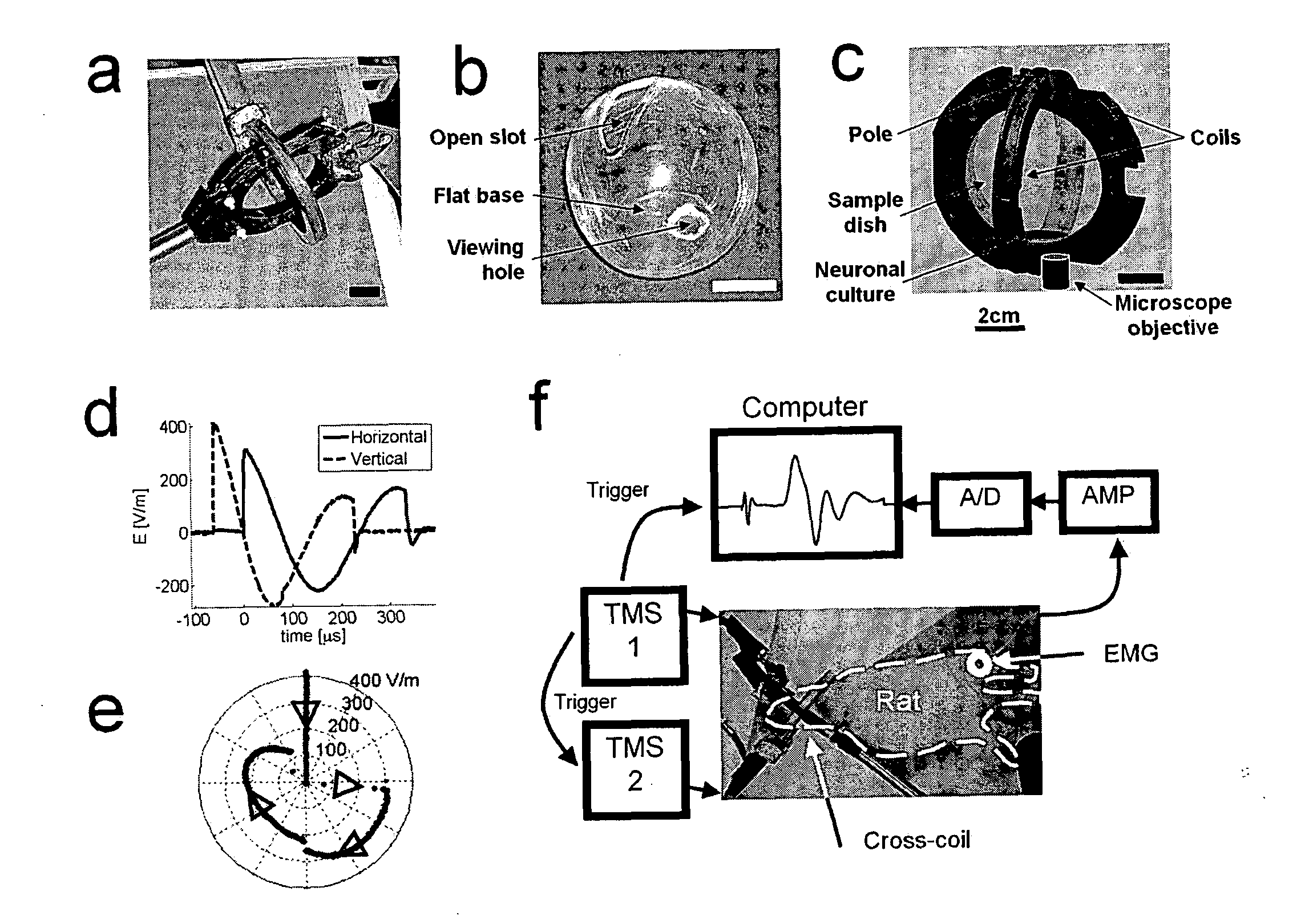
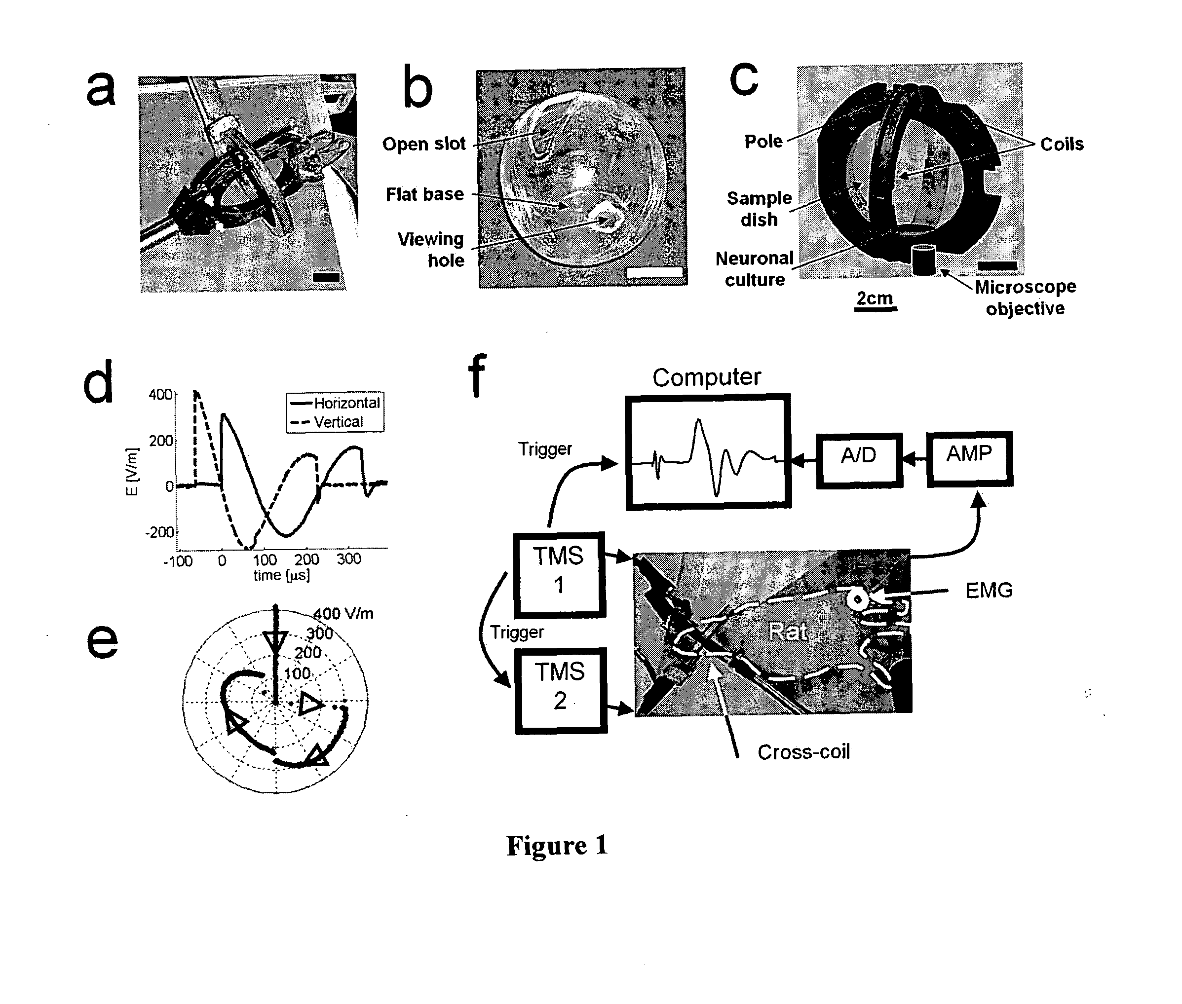
[0204]A rotating electric field was induced by using two independent sets of coils whose magnetic fields are perpendicular to each other and whose currents are phase shifted one from the other by a quarter of a cycle. Introducing a 90° phase lag between the two magnetic sinusoidal pulses, was achieved by precise triggering of two independent power supplies, each controlling a separate figure eight coil.

[0205]Power supplies. The two power supplies used were a Magstim Rapid TMS (Magstim, UK) and a home made stimulator (HMS). The HMS is based on a large 0.1 mF capacitor (Maxwell Laboratories, USA) with maximum voltage load of 22 kV and is able to obtain magnetic fields that are five times stronger than the field supplied at the sample by the commercially available Magstim Rapid. In order to achieve accurate phase lag between the two magnetic pulses, the two power supplies were synchronized using a signal generator (Keithley 3390 50 MHz Arbitrary ...

example 2

Electric Vs. Magnetic Excitation of Neuronal Cultures

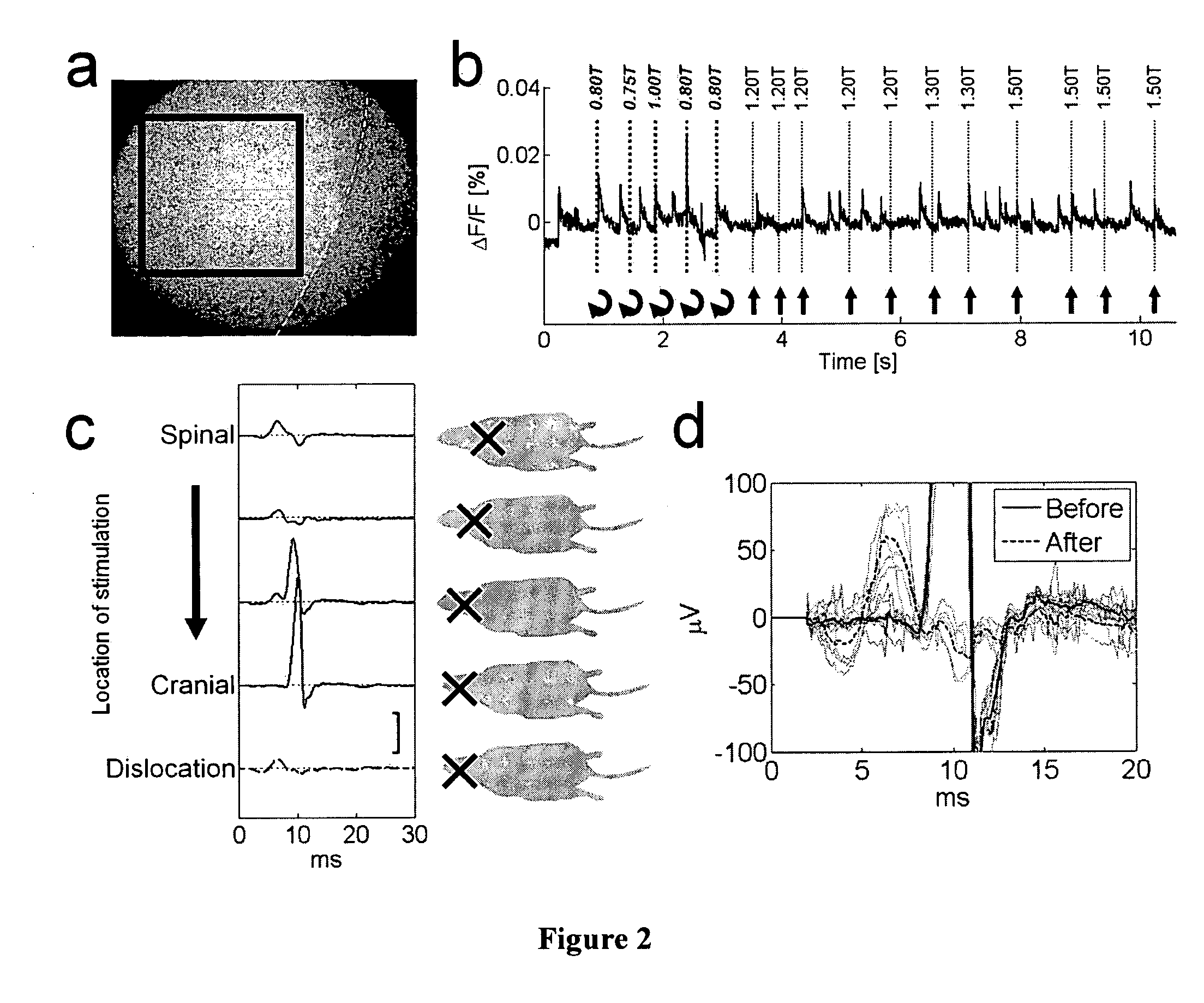
[0241]According to this aspect and in one embodiment, electric stimulation is tested for insight into magnetic stimulation. Because long pulses (˜1 ms) are easy to excite electrically but not magnetically, and since the fundamental mechanisms behind the two modes of simulation are similar, the response of cultures to varying duration of electric pulses was investigated. Based on this, reasonable conclusions and conjectures were made on the mechanism underlying magnetic stimulation.

[0242]To demonstrate the time dependence, cultures that can be stimulated both electrically and magnetically were tested, and compared to those that can be excited only electrically. It naturally turns out that cultures that respond to the magnet respond to short electric pulses. What is not obvious is that cultures that do not respond to magnetic stimulation also do not respond to short pulses, and can be excited only with long electric pulses.

Methods:

E...

example 3

Magnetic Stimulator for Dendritic Excitation

[0260]In one embodiment, dendritic excitation requires magnetic pulses with a rise time of 1 ms, made possible by increasing the capacitance of the stimulator. For this a larger stimulator was constructed with a capacitor C of 4.8 mF and a maximum voltage load of 6.5 kV (3650CMF3480, General Atomics Electronic Systems, USA) capable of delivering about 10 T with a rise time of 1 ms. Two ignitrons, I1 and I2 (NL7703, National Electronics, USA) were used: I1 was used to initiate discharge through the coil and I2 was used to shortcut the coil and stop the discharge through the coil (FIG. 7). In this way, the initiation of a pulse can be controlled with I1 and the termination of a pulse can be controlled by I2.

In one embodiment, capacitors that are used in stimulators of the invention can be commercially available capacitors such as the General Atomics capacitors described in http: / / www.ga-esi.com / EP / capacitors / series-cmf-self-healing-capacitor...


PUM

PropertyMeasurementUnit
degree angleaaaaaaaaaa
capacitanceaaaaaaaaaa
angleaaaaaaaaaa

Abstract

Transcranial magnetic stimulation (TMS) is a remarkable tool for probing the brain. However, it is still unclear why specific regions in the cortex are excitable by TMS while others are not. This invention provides methods and tools for the design of efficient magnetic stimulators. Such stimulators can excite neuronal networks that were not sensitive to stimulation until now. Stimulation can be carried out both in-vitro and in-vivo. Novel systems and techniques of this invention will enable both treatment and diagnostics by stimulating regions of the brain or neuronal assemblies that were previously unaffected by TMS.

Description

FIELD OF THE INVENTION[0001]This invention is related to transcranial magnetic stimulation (TMS), devices, apparatus and methods of use thereof.BACKGROUND OF THE INVENTION[0002]Transcranial magnetic Stimulation (TMS) is the leading noninvasive device for the stimulation of brain and nerve activity. As such, a significant increase in the variety of applications for TMS, from therapeutic treatments for depression or migraine to probing brain activity in a large number of research topics is seen. TMS is a novel and innovative addition to the arsenal of noninvasive probing capabilities and intervention modalities. The development of such probes is one of the major issues of diagnostic and therapeutic approaches to neurology and neurosurgery. The major limitation of TMS is the precision and specificity of its activation region. TMS is currently able to excite only specific areas in the brain, mostly in the cortex. It is still not obvious what determines the accessibility of brain areas t...

Claims


Application Information

Patent Timeline
Patent Type & Authority Applications(United States)
IPC IPC(8): A61B5/055A61B5/0476C12M1/42A61N2/02C12N13/00C12Q1/02
CPCA61N1/08A61N1/36025A61N2/02A61N1/40A61N2/006A61N1/36082A61B5/0036
Inventor MOSES, ELISHAROTEM, ASSAF
Owner YEDA RES & DEV CO LTD
Learn More