Unlock instant, AI-driven research and patent intelligence for your innovation.
Moving mechanism
Inactive Publication Date: 2012-03-01
HITACHI LTD
View PDF26 Cites 26 Cited by
Summary
Abstract
Description
Claims
Application Information
AI Technical Summary
This helps you quickly interpret patents by identifying the three key elements:
Problems solved by technology
Method used
Benefits of technology
Benefits of technology
[0010]According to the present invention, with the moving mechanism connecting wheels to the car frame and for moving, it is possible to travel with stability while keeping the car frame to be in parallel with, even on the inclined road surface.
Problems solved by technology
For this purpose, there can be considered a means, i.e., mounting the suspensions thereon; however, with this, though it is possible to absorb the unevenness on the road by means of the suspensions, but in case when running on the inclined road, the car frame is inclined down to a lower side of the inclined road, and therefore it is impossible to keep the car frame horizontal or in parallel with.
Also, in case where the distance between the wheels is small, which are provided in the front and the rear or on the left and the right, an amount of sinking or subsidence of the suspension becomes large, either in the front or the rear, or on the left or the right, due to a centrifugal force during a cornering operation, or the disturbances, such as, the unevenness and the inclination of the road surface, and thereby bringing about a problem of increasing a possibility of falling down and losing the stability.
However, a driving force of the actuator must be generated, always, even when running on a flat road, and this brings about a problem of enlarging a consumption of electric power.
Further, the actuator must be provided for each of the suspensions, and this also brings about a problem of increasing a number of parts and the weight thereof.
Method used
Image
Click on the blue label to locate the original text in one second.
Reading with bidirectional positioning of images and text.
Examples
embodiment 1
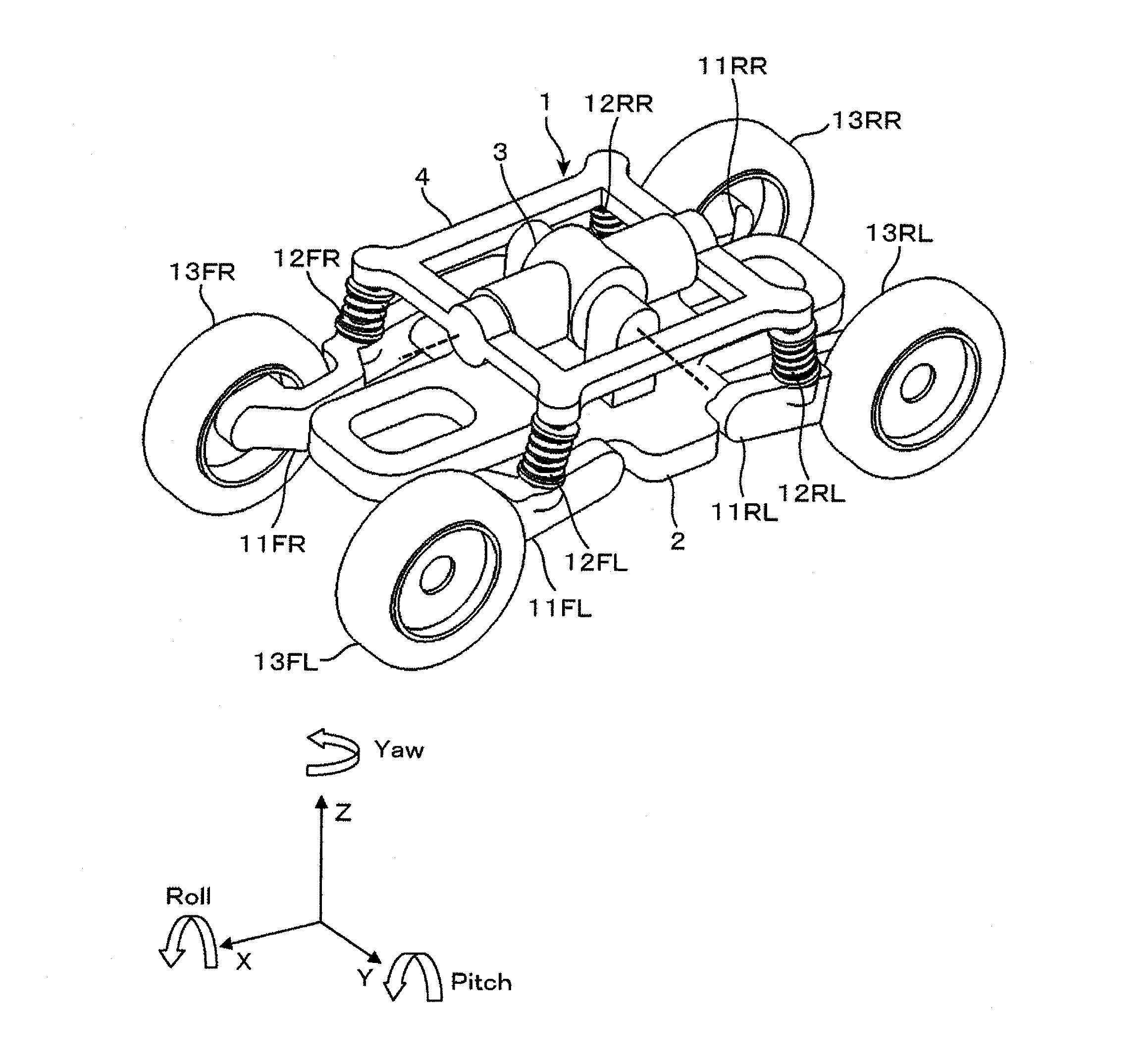
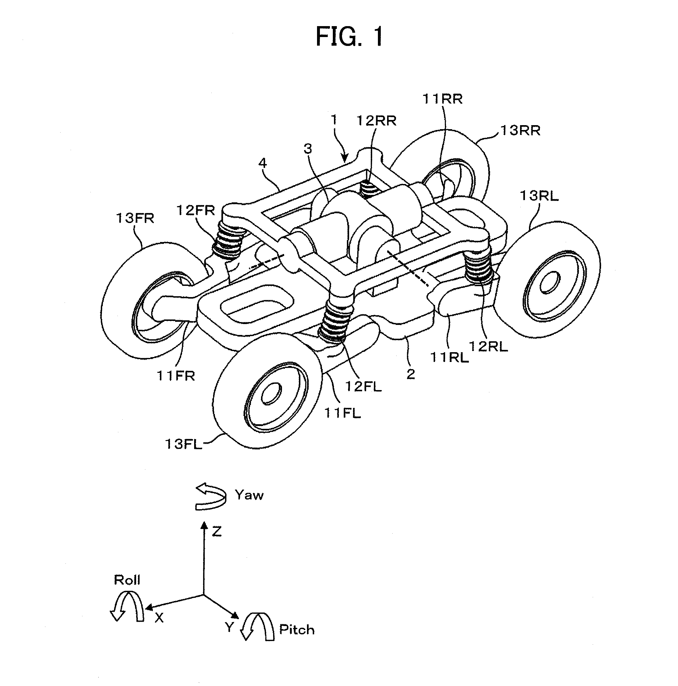
[0026]As is shown in FIG. 1, the moving mechanism 1 according to the present embodiment comprises four (4) pieces of swing arms 11FL, 11FR, 11RL and 11RR, at four corners of a car frame 2, each being able to rotate only into the pitch direction, and wheels 13FL, 13FR, 13RL and 13RR, at one ends of the swing arms 11FL, 11FR, 11RL and 11RR in the longitudinal direction thereof, respectively. In a middle of the longitudinal direction of the swing arms 11FL, 11FR, 11RL or 11RR are connected suspensions 12FL, 12FR, 12RL and 12RR, respectively, each having degrees of freedom in the pitch / roll directions, and the other ends of the suspensions 12FL, 12FR, 12RL and 12RR in the longitudinal direction thereof are suspended at the four (4) corners of the table 4, each having the degrees of freedom, in both the pitch and roll directions. The table 4 is attached around a central portion of the car frame 2, to be able to jolt in both the pitch and roll directions, by an actuator 3 of 2-degrees of ...
embodiment 2
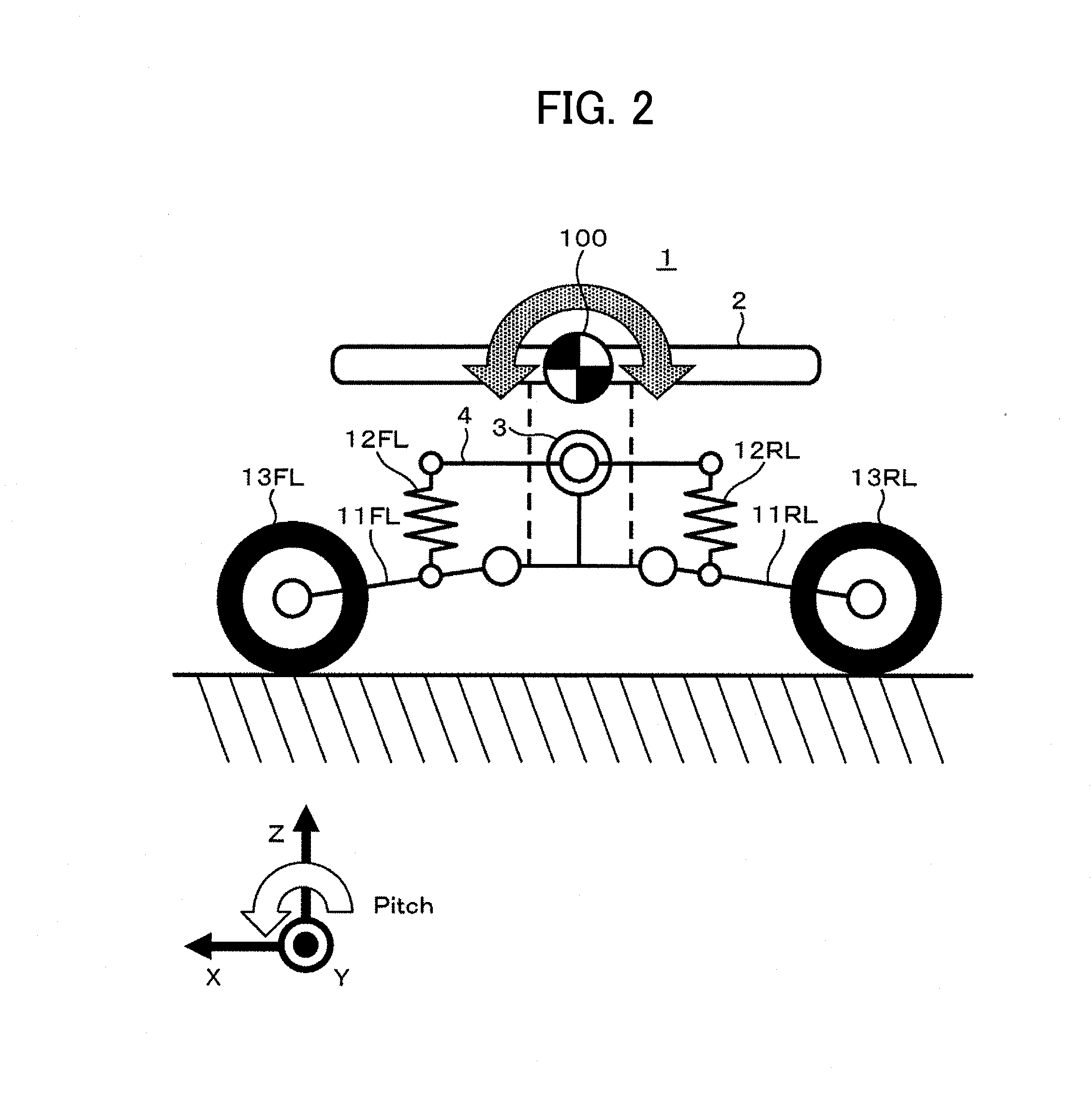
[0041]Next, explanation will be given on the suspension of the moving mechanism according to an embodiment 2.
[0042]Depending on the use of the moving mechanism 1, the unevenness or the inclination of the road surface, on which the moving mechanism travels, it is not necessity to take the pitching / rolling of the moving mechanism 1 into the consideration, and there is a case where it is enough to suppress either one, i.e., the rolling or the pitching.
[0043]In the embodiment 1, the table 4 is attached on the car frame 2, being movable in two (2) degrees of freedom, i.e., the pitch / roll directions; however, in the embodiment 2, the table 4 is attached thereon, being movable in either one direction, the pitch direction or the roll direction, by means of an actuator 31 of 1-degree of freedom.
[0044]Also, the control is executed along with the control block diagram shown in FIG. 4 and the flowchart shown in FIG. 5, in the similar manner to that of the embodiment 1; however in the flowchart ...
PUM
Abstract
A moving mechanism for running stably, with keeping a car frame horizontal even on a road surface inclined, while absorbing disturbances from unevenness on the road surface, comprises a car frame attached with wheels for running, wherein each of the wheels is attached to a car body through a swing arm, and an appropriate control is made on an inclination of a table rotatable in pitch / roll directions, to which coil springs for supporting the swing arms, respectively, are suspended; thereby achieving the moving mechanism for running stably, with keeping the car frame horizontal.
Description
[0001]This application relates to and claims priority from Japanese Patent Application No. 2010-193063 filed on Aug. 31, 2010, the entire disclosure of which is incorporated herein by reference.BACKGROUND OF THE INVENTION[0002]The present invention relates to suspensions of a moving mechanism for running or traveling on a rough road having unevenness on wheels, and in particular, it relates to the mechanism for traveling on it while keeping a body thereof horizontal or in parallel with a ground surface.[0003]As a technology for traveling with stability, while absorbing such unevenness on the traveling road and / or an inclination thereof is already known, for example, in the following Patent Document 1 that will be described below.[0004]In the method disclosed in the Patent Document 1, there is disclosed a moving mechanism for controlling each of cylinders, appropriately, depending on the inclination of a car body, while suspending each of the wheels from the car body through those cy...
Claims
Application Information
Patent Timeline
Application Date:The date an application was filed.
Publication Date:The date a patent or application was officially published.
First Publication Date:The earliest publication date of a patent with the same application number.
Issue Date:Publication date of the patent grant document.
PCT Entry Date:The Entry date of PCT National Phase.
Estimated Expiry Date:The statutory expiry date of a patent right according to the Patent Law, and it is the longest term of protection that the patent right can achieve without the termination of the patent right due to other reasons(Term extension factor has been taken into account ).
Invalid Date:Actual expiry date is based on effective date or publication date of legal transaction data of invalid patent.

