Pressure Relief Valve For A Round Baler

a technology of pressure relief valve and baler, which is applied in the direction of valve operating means/release devices, paper/cardboard articles, manufacturing tools, etc., can solve the problems of relative high opening pressure, permanent excitation of electromagnet, damage to baler, etc., and achieve the effect of increasing the bias tension of the spring and thus the opening pressur

Active Publication Date: 2012-03-08
DEERE & CO
View PDF3 Cites 2 Cited by
  • Summary
  • Abstract
  • Description
  • Claims
  • Application Information

AI Technical Summary

Benefits of technology

[0013]When the electromagnet is energized it advantageously biases the closure element similarly into a closure position blocking the passage. In such a configuration, the construction according to the invention of the adjustment element and the valve body is especially useful, because, through the removal of the electromagnet, the increase of the opening pressure resulting from the electromagnet for a defective permanent excitation is avoided. The biasing of the spring corresponds to a minimum value when the electromagnet is fixed on the valve body. The minimum value advantageously corresponds to an opening pressure of 0 bar. The bias tension of the spring (and thus the opening pressure) can be increased by the adjustment element relative to the minimum value only when the electromagnet has been removed. In this way, the full displacement range of the pressure-relief valve is provided to the electromagnet.

Problems solved by technology

In both of the above-mentioned balers, a failure or interference in the electronic controller of the pressure-relief valve results in a relatively high opening pressure.
Now, if the operator inadvertently sets the opening pressure of the pressure-relief valve even higher, then it is possible that a structurally specified maximum pressure in the hydraulic cylinder is exceeded, which could result in damage to the baler.
This problem occurs to an elevated degree if the electromagnet (like in the embodiment according to FIG. 3 of U.S. Pat. No. 4,611,535) in the energized state increases the opening, and the error in the electronics leads to a permanent excitation of the electromagnet.

Method used


Image

  • Pressure Relief Valve For A Round Baler
  • Pressure Relief Valve For A Round Baler
  • Pressure Relief Valve For A Round Baler

Examples


Embodiment Construction

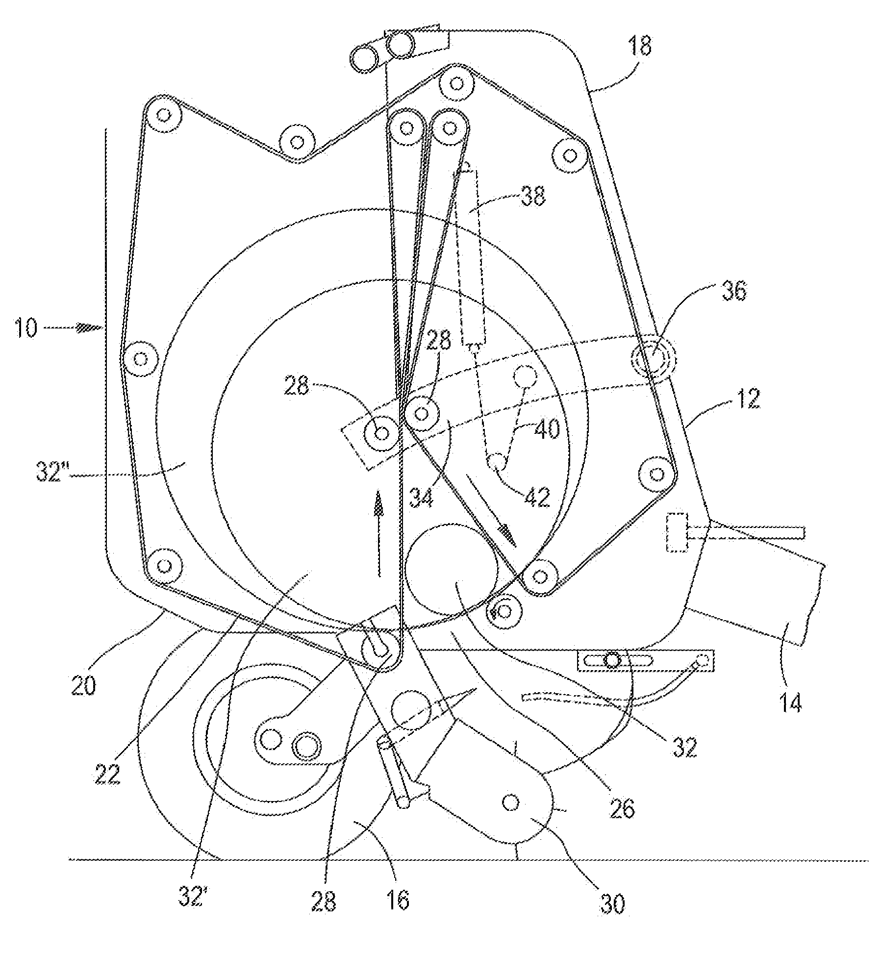
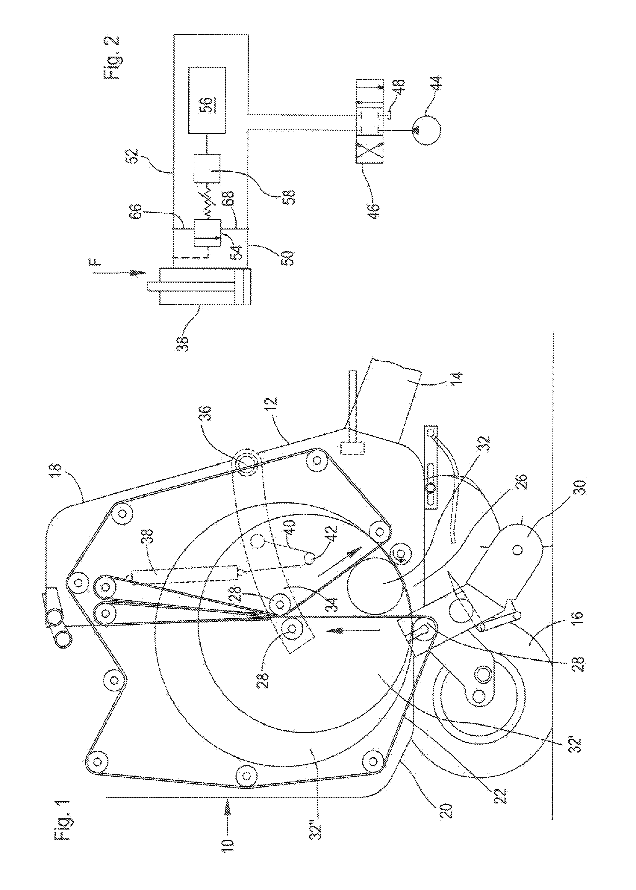
[0020]FIG. 1 shows a round baler 10 with a housing 12 that can be attached to a tractor (not shown) by means of a drawbar 14, in order to be pulled across a field in a driving direction toward the right with respect to FIG. 1, and is supported on wheels 16. The housing 12 is assembled from a front, rigid housing half 18 and a rear, pivoting housing half 20 that are pivotably connected to each other in a joint at the top. The housing 12 carries a plurality of rollers. Endless bale forming elements 22 that are arranged one next to the other run over the rollers. These bale forming elements mostly encompass, together with side walls of the housing 12, a bale chamber 24. In this embodiment, the bale forming elements 22 are constructed as belts. In the lower region of the bale chamber 24 there is an inlet 26 that is bounded at the back by a roller 28 and material taken up by a pick-up 30 can enter into the bale chamber 24.

[0021]The round baler 10 comprises several bale forming elements 2...


PUM


Abstract

A pressure-relief valve is provided. The pressure-relief valve having a valve body with a passage that can be closed by a moving closure element. An electromagnet is mounted detachably on the valve body and interacts with an armature in driving connection with the closure element. A spring interacts with the closure element the bias tension of which can be changed by an adjustment element that can be moved manually relative to the valve body. The adjustment element and the valve body are constructed such that a manual change of the bias tension of the spring by means of the adjustment element is then possible only when the electromagnet is detached from the valve body. Also provided is a round baler employing such a pressure-relief valve.

Description

FIELD OF THE INVENTION[0001]The invention herein relates to a pressure-relief valve having a valve body with a passage that can be closed by a moving closure element. An electromagnet interacts with a moving armature in driving connection with the closure element. A spring interacts with the closure element, a biasing tension of the spring being changeable by an adjustment element that can be moved manually relative to the valve body. The invention further relates to a round baler equipped with such a pressure-relief valve.BACKGROUND OF THE INVENTION[0002]In round balers of variable bale chamber design, the tension of the bale forming elements (e.g. belts) is typically defined by a hydraulic cylinder that interacts with a moving tension arm that carries a deflection roller abut which, in turn, the bale forming elements revolve (normally one or more belts or bar-chain conveyors). The pressure in the hydraulic cylinder is normally controlled by way of a pressure-relief valve whose ope...

Claims


Application Information

Patent Timeline
Patent Type & Authority Applications(United States)
IPC IPC(8): A01F15/07A01F15/08F16K31/02
CPCA01F15/0833
Inventor HUMBERT, CLEMENT
Owner DEERE & CO
Why Eureka
Try Eureka