[0007] According to the invention, the flow restrictor has diverting body and the force generated by the diversion of the volume flow at the diverting body is used to adjust the flow restrictor. In doing so, the contour of the diverting body (54) is designed expediently so that the largest possible adjusting force is yielded with the lowest possible flow resistance.
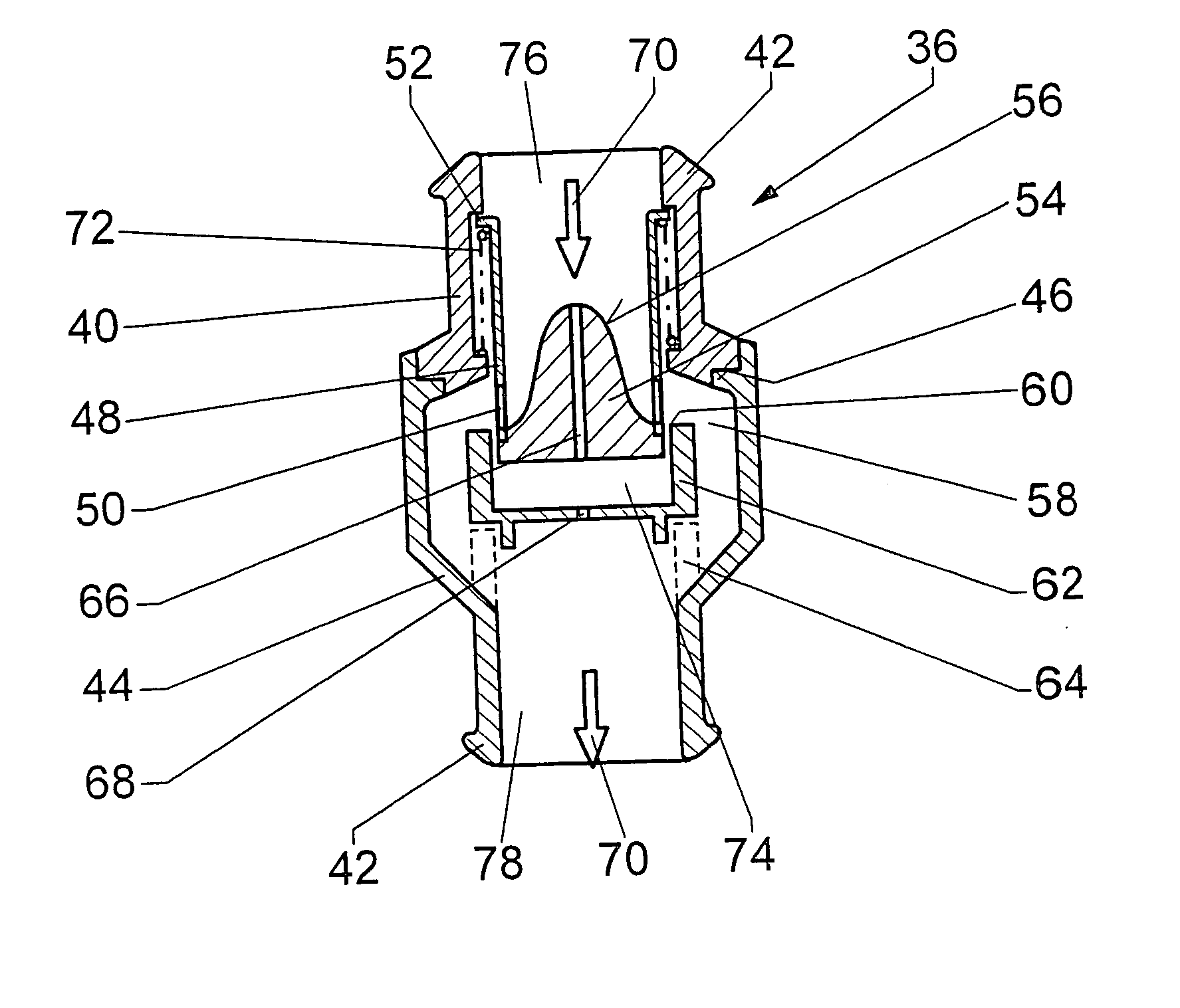
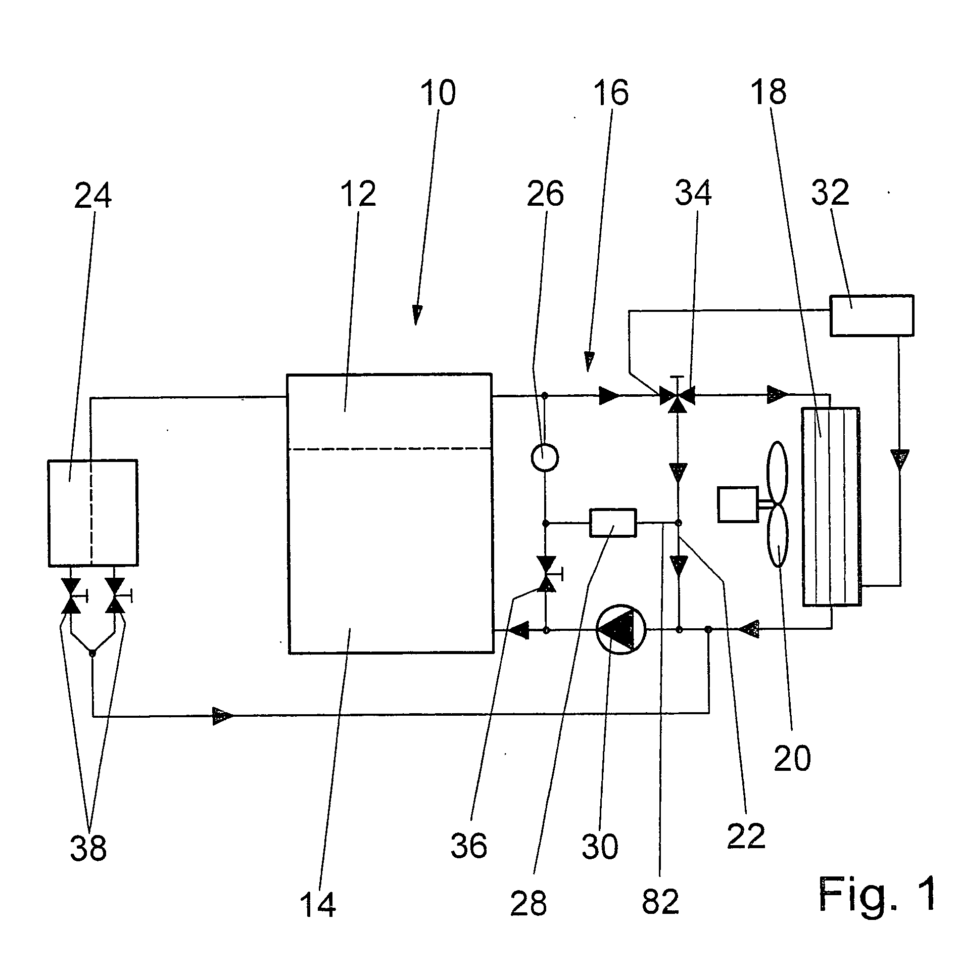
[0008] If the flow restrictor is comprised of a control cylinder and a base part, the base part can serve as a diverting body in that its contour projects into the control cylinder on its inflow side and is flush at its outflow side and approximately tangentially adjacent at the control openings. Because of this form of base part, a volume flow acting on the flow restrictor is diverted in terms of its direction. Due to the diversion, the volume flow exercises a force on the flow restrictor whose size is a function of the speed of the volume flow. As a result, the flow restrictor is adjusted as a function of the volume flow so that the throttle openings diminish with increasing speed. In contrast to known volume flow control valves, in which the adjusting force is yielded primarily from the static pressure difference at the wetted surfaces of the flow restrictor, with the volume flow control valve in accordance with the invention, the dynamic flow forces are used in the diversion of the flow. In the case of low flow resistance of the volume flow control valve in accordance with the invention, greater forces occur on the flow restrictor as a result of this, so that it is simple to dimension for different application cases, particularly for use in heating / cooling cycle with thermal management. In this case, only small volume flows are present in some branches, whose flow force is not adequate to create a pressure drop required for known volume flow control valves. Therefore, a volume flow control valve in accordance with the invention can advantageously restrict the coolant volume flow through coolant-cooled accessories, such as a starter or a generator, independent of the pump capacity of the coolant pump in the main cycle, to the maximum volume flow required for cooling.
[0009] In addition to the contour of the base part, the inner contour of the control cylinder influences the flow speed and the diversion and therefore the adjusting force acting on the flow restrictor. For this reason, the inner contour can run conically towards the contour of the base part. The pressure loss at the flow restrictor, which should be as low as possible, acts against the adjusting force in order to keep the flow resistance within defined limits. As a result, the invention provides for a pressure compensation chamber beneath the flow restrictor and pressure compensation bore holes in the base part, via which a static pressure compensation between the inflow side and the outflow side of the volume flow control valve is achieved.
[0010] If, with increasing volume flow through the flow restrictor, the adjusting force exceeds an opposing spring tension, the flow restrictor dips into a stationary guide cylinder, which has a control edge on its end facing the flow restrictor, which now covers the control openings by the amount of the adjusting path. A throttle point is thereby reduced and the desired volume flow is adjusted. Within an operating range, the volume flow increases more or less with further increased pressure in accordance with the spring characteristic and the size of the adjusting path between the completely opened and completed closed valve position. In an ideal case it remains constant after the target volume flow has been reached. In order to come as close as possible to the ideal case, the control openings should already be significantly reduced with a slight increase of the adjusting force acting on the flow restrictor. This is achieved with a long spring that has a flat characteristic curve, with which the spring tension only increases by a very small amount with a small adjusting path. The control openings have a slight extension in the movement direction in order to keep the adjusting path small.
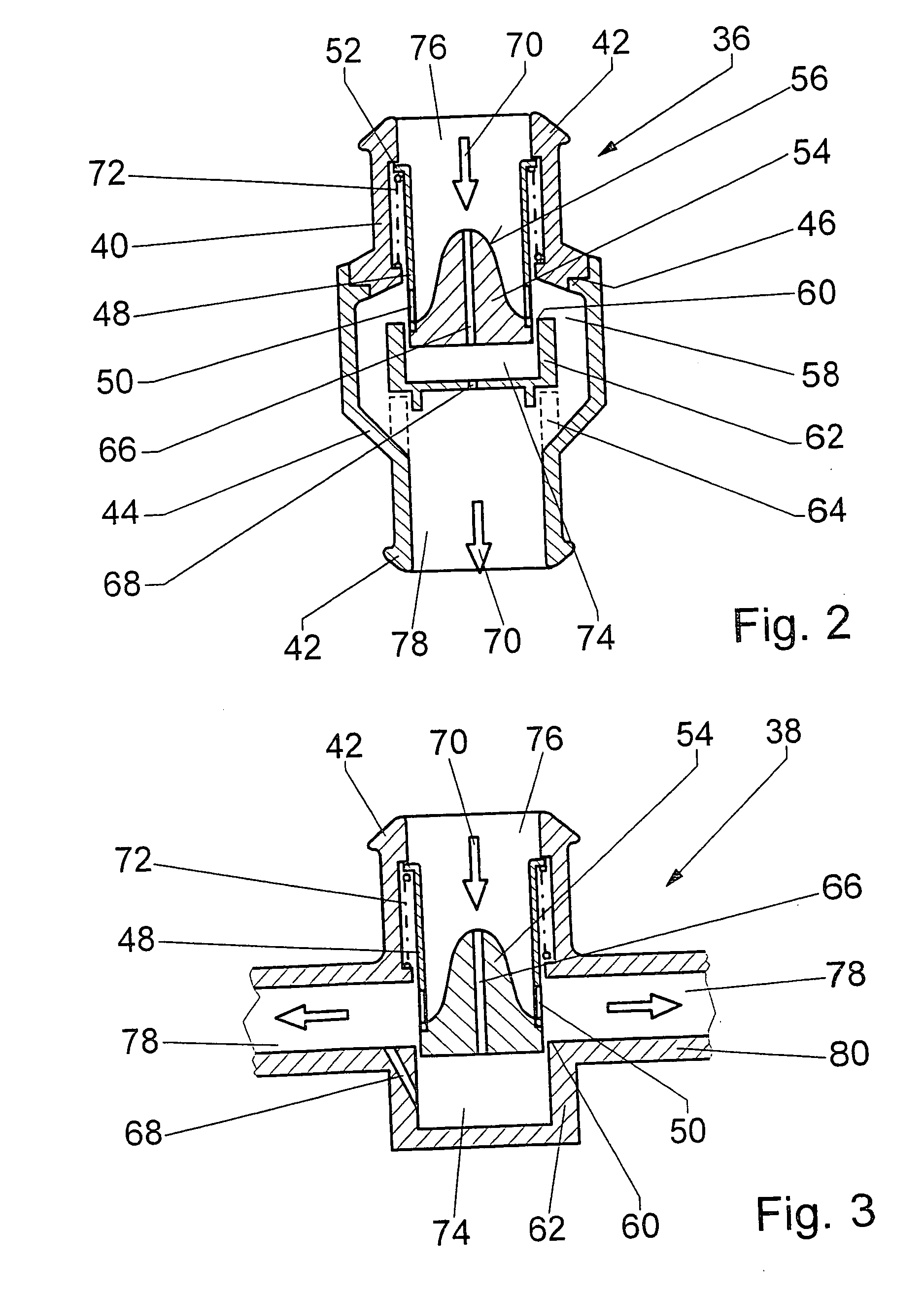
[0011] The volume flow characteristic curve of the volume flow control valve in accordance with the invention is adapted qualitatively and quantitatively to the requirements of a specific unit by a corresponding shaping of the base part on the flow restrictor, pressure compensation bore holes with a defined diameter and a special spring characteristic. With corresponding modifications, the volume flow control valve can be used in different branches of the cooling cycle and can therefore be manufactured cost effectively and in large unit numbers. Moreover, it is comprised of fewer components as compared with known valves, because otherwise customary devices to set the spring prestress or check valves are eliminated. The volume flow control valve is constructed to be compact and has a two-piece housing, whereby an upper and a lower housing part each have a hose connection so that the valve can be largely integrated into the area of the hose connection of a to-be-cooled unit in an advantageous manner and no additional construction space is required. In one embodiment of the invention, the volume flow control valve is designed structurally in such a way that it can be integrated into a cooling jacket of a unit. There are additional possibilities for use as a result.

