Rotary switch mechanism

a rotary switch and mechanism technology, applied in the direction of electric switches, electric apparatuses, legends, etc., can solve the problem that the gesture of controlling these functions cannot be directly perceived through the user's senses, and achieve the effect of low abrasion

Inactive Publication Date: 2012-03-08
PRIMAX ELECTRONICS LTD
View PDF12 Cites 36 Cited by
  • Summary
  • Abstract
  • Description
  • Claims
  • Application Information

AI Technical Summary

Benefits of technology

[0010]The present invention also provides a

Problems solved by technology

If some specified functions, for example the functions of zooming in/out an image or rotating the image, are controlled by pressing the

Method used


Image

  • Rotary switch mechanism
  • Rotary switch mechanism
  • Rotary switch mechanism

Examples


Embodiment Construction

[0027]The present invention provides a rotary switch mechanism for use in various electronic devices.

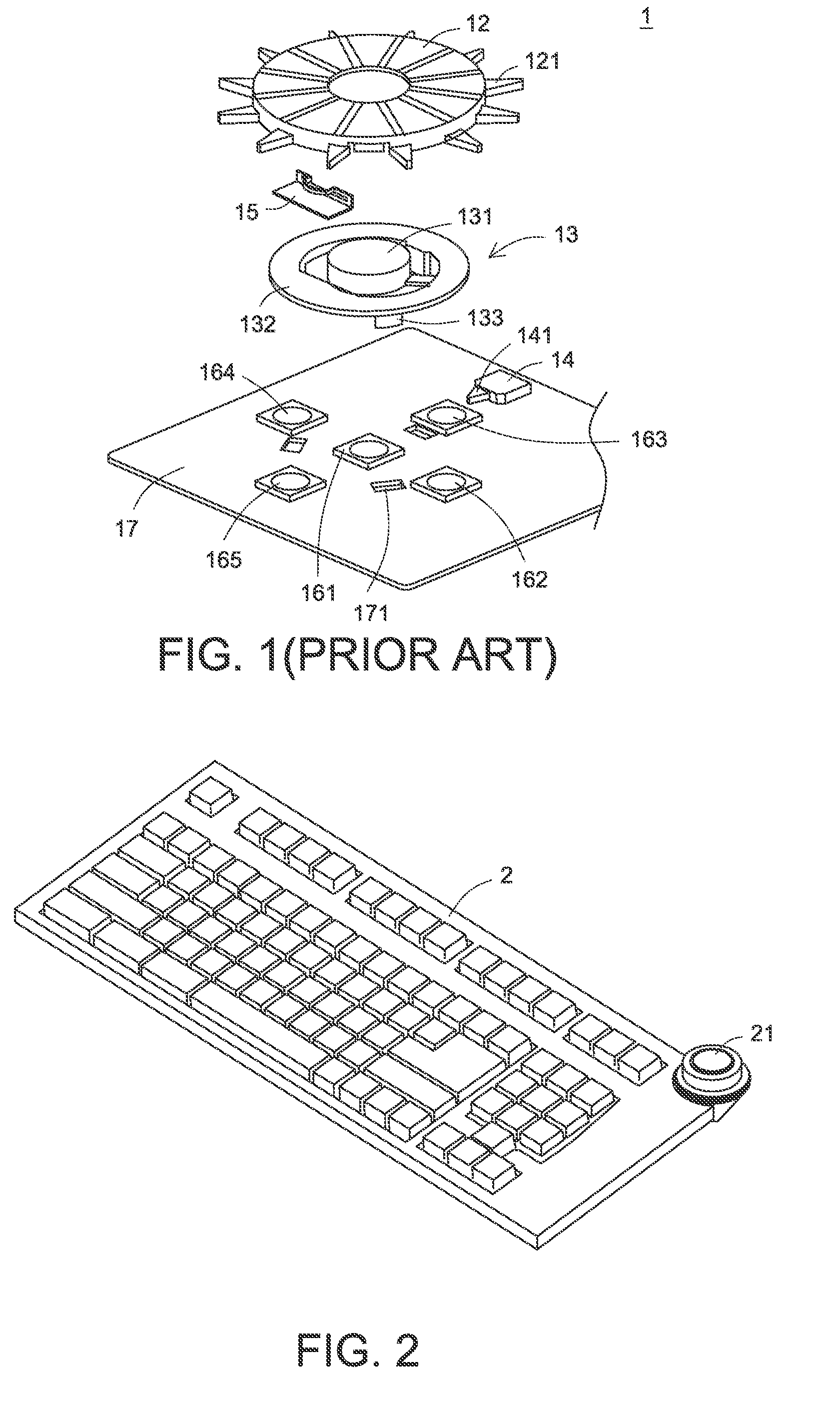
[0028]FIG. 2 is a schematic perspective view illustrating a rotary switch mechanism 21 for use in an input device 2 according to an embodiment of the present invention. In this embodiment, the input device 2 is a computer keyboard.

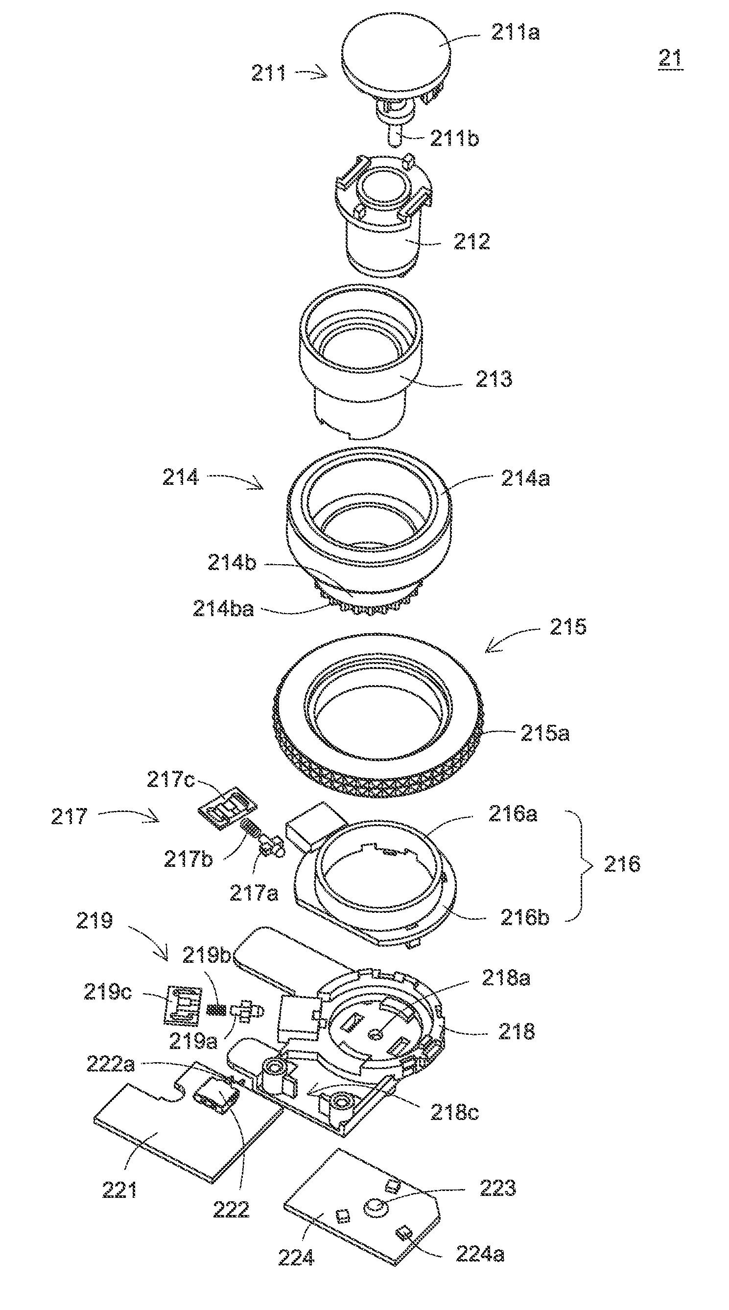
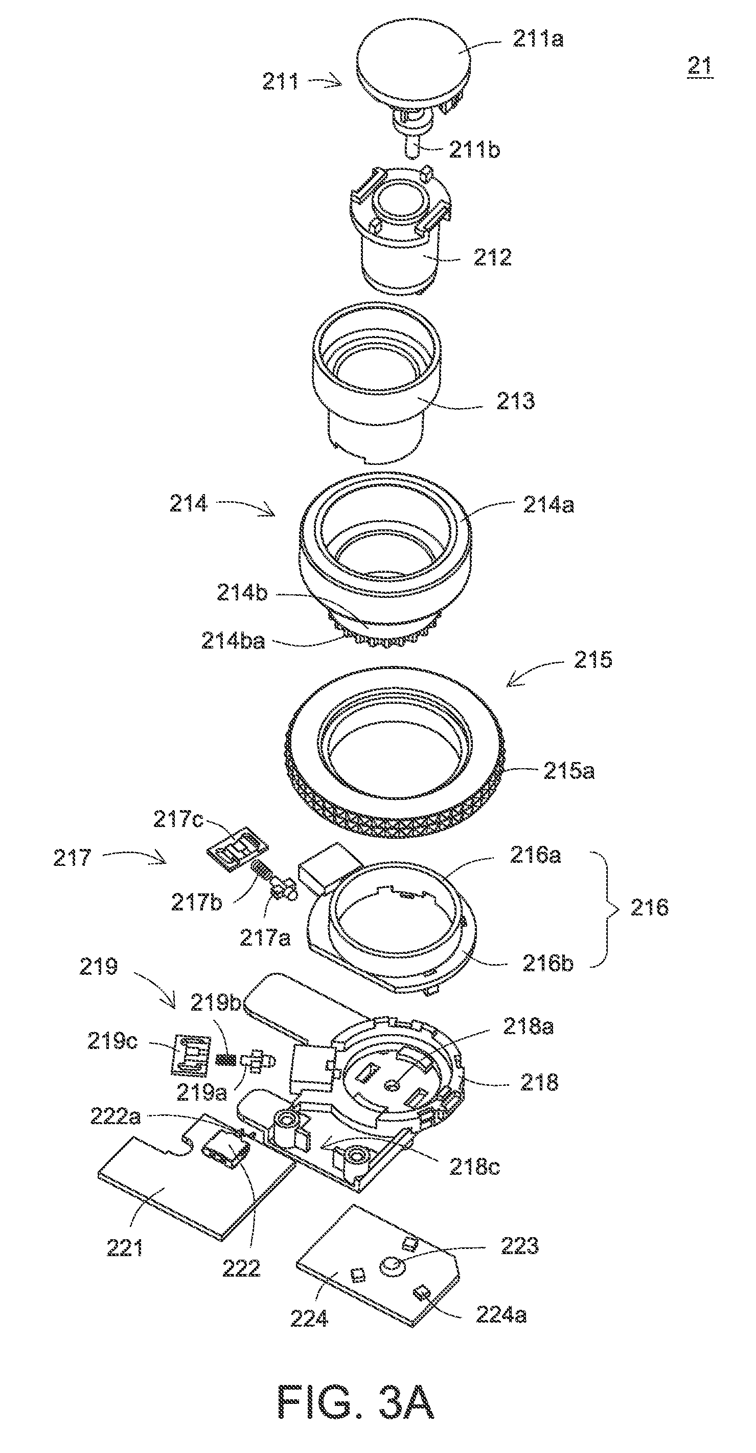
[0029]Hereinafter, the detailed structure of the rotary switch mechanism 21 will be illustrated with reference to FIGS. 3A and 3B. As shown in FIGS. 3A and 3B, the rotary switch mechanism 21 comprises a push button 211, a hollow cylinder 212, a light-guiding element 213, a first rotatable member 214, a second rotatable member 215, a supporting member 216, a first sustaining member 217, a base 218, a second sustaining member 219, a first switch 220, a second circuit board 221, a second switch 222, a third switch 223 and a first circuit board 224.

[0030]The push button 211 comprises a pressing surface 211a and a pressing rod 211b. The hollow cylinder 212 has a...


PUM


Abstract

A rotary switch mechanism includes a hollow cylinder, a base, a push button, a first rotatable member, a second rotatable member, a first switch, a second switch and a third switch. The base is disposed under the hollow cylinder. The first rotatable member is sheathed around the hollow cylinder. The second rotatable member is sheathed around the first rotatable member. The first switch is disposed beside the first rotatable member. The second switch is disposed beside the second rotatable member. The third switch is mounted on a first circuit board, which is disposed under the base. The first rotatable member and the first switch interact with each other to generate a first rotating signal. The second rotatable member and the second switch interact with each other to generate a second rotating signal. The third switch is triggered by the pressing rod to generate a pressing signal.

Description

FIELD OF THE INVENTION[0001]The present invention relates to a rotary switch mechanism, and more particularly to a two-layered rotary switch mechanism.BACKGROUND OF THE INVENTION[0002]A rotary switch mechanism is usually installed in for example a computer peripheral device to generate a control signal. In response to the control signal, a specified function (e.g. a sound volume adjusting function) may be executed.[0003]FIG. 1 is a schematic exploded view illustrating a conventional rotary switch mechanism. The conventional rotary switch mechanism is disclosed in for example U.S. Pat. No. 7,750,256. As shown in FIG. 1, the conventional rotary switch mechanism 1 comprises a dial assembly 12, a push button 13, a rotary switch 14, an elastic element 15, five dome switches 161˜165 and a circuit board 17.[0004]The dial assembly 12 comprises plural projecting parts 121. The push button 13 comprises a central button part 131 and a ring-shaped part 132. The ring-shaped part 132 is connected...

Claims


Application Information

Patent Timeline
IPC IPC(8): H01H9/00
CPCH01H19/025H01H25/065H01H2019/143H01H2239/024H01H2219/0622H01H2239/022H01H2025/045
Inventor CHOU, KUAN-NAN
Owner PRIMAX ELECTRONICS LTD
Why Eureka
Try Eureka