Weld material ignition

Inactive Publication Date: 2012-03-08
ALGHUSAIN FADY AMEER
View PDF21 Cites 20 Cited by
  • Summary
  • Abstract
  • Description
  • Claims
  • Application Information

AI Technical Summary

Problems solved by technology

Exothermic welded connections generally are immune to thermal conditions which can cause mechanical and compression joints to become loose or corrode.
The exothermic reaction produces a large amount of heat.
Unfortunately, exothermic mixtures of this type do not react spontaneously and need a method of initiating the reaction.
However, because of the starting powder's low ignition temperature an

Method used


Image

  • Weld material ignition
  • Weld material ignition
  • Weld material ignition

Examples


Embodiment Construction

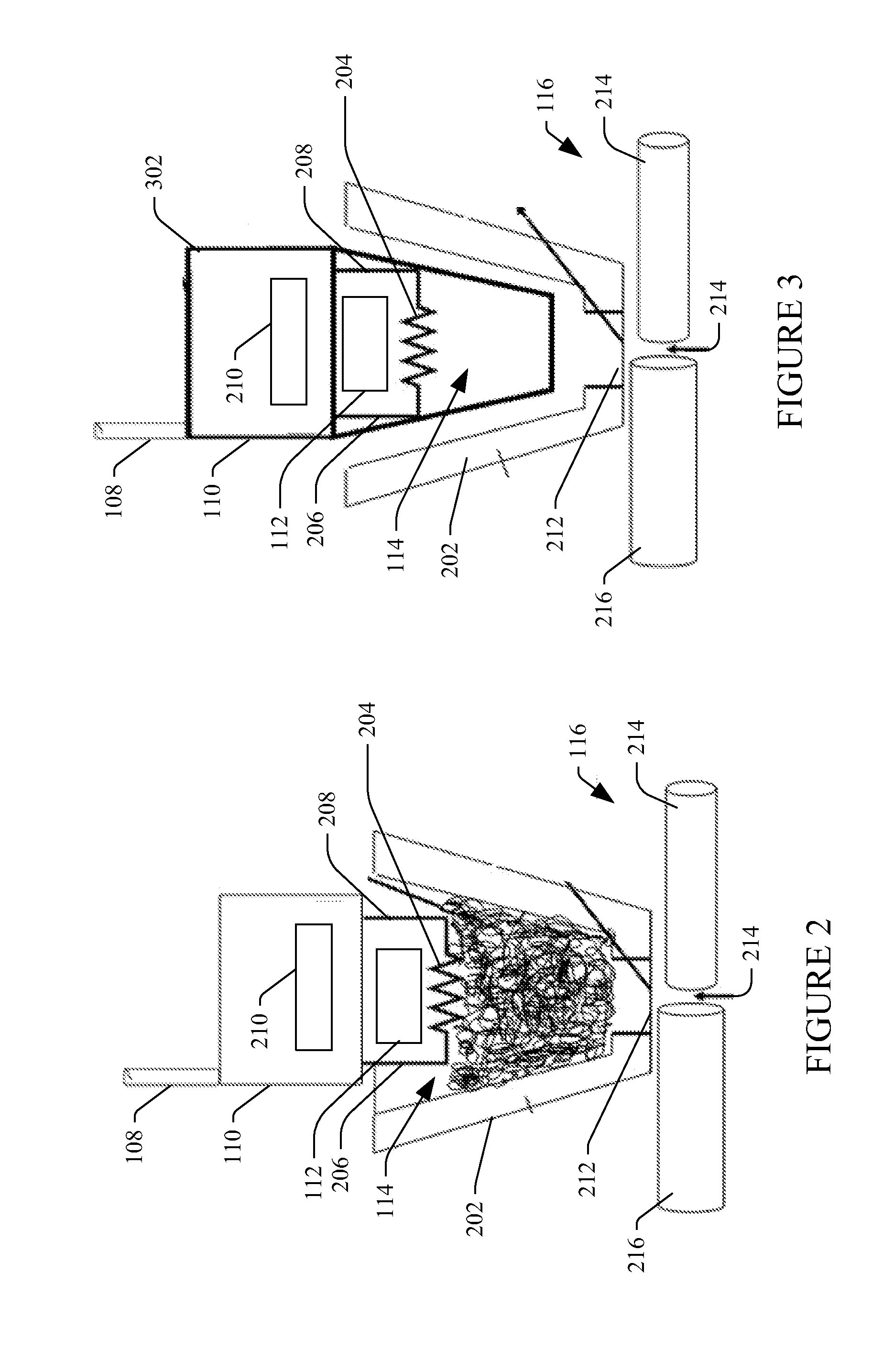
[0022]The following generally relates to wireless ignition of an exothermic chemical reaction in connection with a welding application, or exothermic based welding. Various non-limiting applications include, but are not limited to, forming electrically weld connections, railroad tracks welding, welding two pieces of copper objects, welding two pieces of rail road tracks, etc.

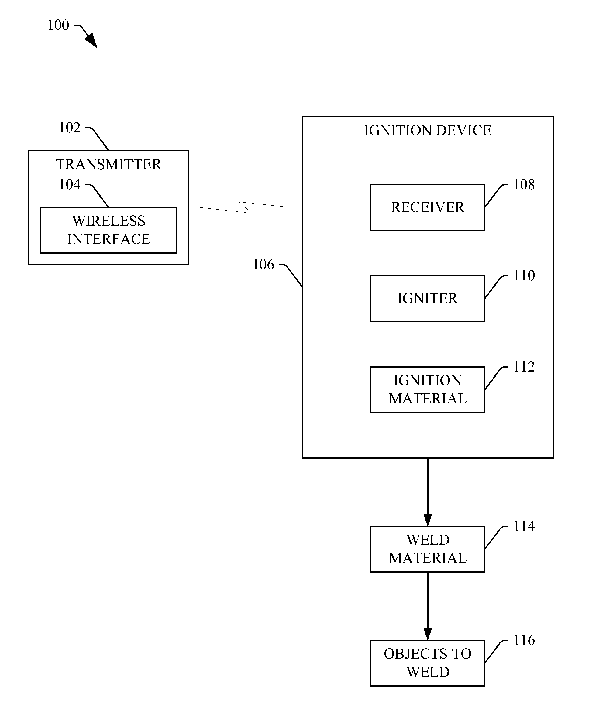
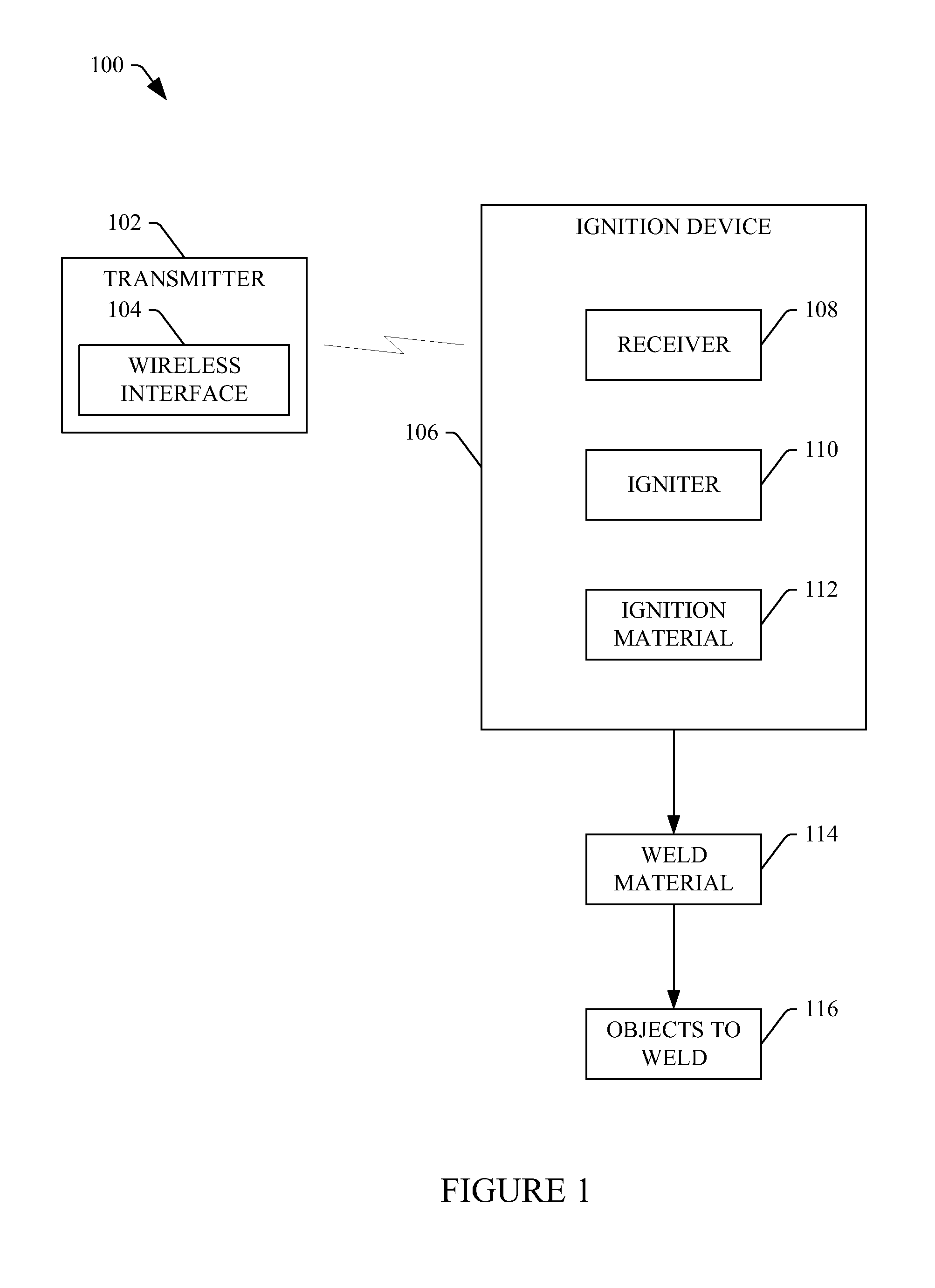
[0023]FIG. 1 illustrates an example wireless ignition system 100.

[0024]The system 100 includes a transmitter 102. The illustrated transmitter 102 at least includes a wireless interface 104 for wireless communication. Suitable wireless interfaces include, but are not limited to, radio frequency, optical, infrared, laser, and / or other wireless interfaces. Optionally, the transmitter 102 may also include one or more physical electrical contacts for non-wireless communication. In some embodiments, the transmitter 102 also includes a micro-processor that facilitates communication and memory that stores computer reada...


PUM

PropertyMeasurementUnit
Energyaaaaaaaaaa
Heataaaaaaaaaa

Abstract

A weld ignition system includes a wireless receiver that wirelessly receives a weld ignition activation signal. The weld ignition system further includes igniter that ignites a weld ignition material in response to the wireless receiver wirelessly receiving the weld ignition activation signal. The ignited weld ignition material initiates exothermic based welding of a weld material.

Description

TECHNICAL FIELD[0001]The following generally relates to weld material ignition.BACKGROUND[0002]Exothermic welding has become recognized globally as a preferred way to form top quality welding. One benefit of exothermic welding is the low resistance between rigid metallic rods for bonding and grounding applications. Exothermic welded connections generally are immune to thermal conditions which can cause mechanical and compression joints to become loose or corrode. They are also recognized for their durability and longevity. The process fuses together the parts or conductors to provide a molecular bond, with a current carrying capacity equal to that of the conductor. Such connections are widely used in grounding systems enabling the system to operate as a continuous conductor with lower resistivity. Examples of self propagating exothermic reactions for exothermic welding include the CADWELD® process (Erico International Corporation, Solon, Ohio) and the THERMIT® process (Th. Goldschmi...

Claims


Application Information

Patent Timeline
IPC IPC(8): B23K31/02B23K37/00
CPCB23K25/00B23K23/00
Inventor ALGHUSAIN, FADY AMEER
Owner ALGHUSAIN FADY AMEER
Why Eureka
Try Eureka