Apparatus, systems and methods for producing particles using rotating capillaries

a technology of rotating capillaries and apparatuses, applied in glass making apparatuses, manufacturing tools, transportation and packaging, etc., can solve the problems of limiting the fluid feed rate of such devices, the width of the capillary should be sufficiently small, and the particle formation rate of such devices tends to be relatively large, so as to achieve the effect of reducing the amount of air shear, reducing the size of the capillary, and increasing the liquid feed ra

Inactive Publication Date: 2012-03-08
GABAE TECH
View PDF0 Cites 36 Cited by
  • Summary
  • Abstract
  • Description
  • Claims
  • Application Information

AI Technical Summary

Benefits of technology

[0010]Furthermore, U.S. Pat. No. 4,643,852 (filed by the inventor on Dec. 30, 1985) describes an apparatus for generating gas bubbles in a liquid. The apparatus includes at least one rotatable member, in the shape of a disc or ring, which is wettable by the liquid and rotatable therein at an edge velocity of at least 70 feet per second. The upper surface of the rotatable member is parallel to, and spaced from, a stationary plate to form a shear zone. Gas, or some other fluid, is supplied proximate the upper surface of the rotatable circular member to form the bubbles. Optimized relationships between the radius of the disc or ring and its speed of rotation are disclosed to enhance the efficiency of operation of the apparatus.
[0015]The rotor assembly may include at least three plates (including an upper plate, a lower plate, and at least one intermediate plate) having at least two pairs of opposing planar surfaces, each pair of opposing planar surfaces spaced apart by a gap distance and defining a capillary therebetween. The edges of at least one of the plates (e.g. the intermediate plate(s)) may be bifurcated so as to provide two effective sets of emission surfaces on each plate and thereby double the throughput of the liquid and conversion into particles.
[0034]In some embodiments, the at least one gas includes pollutants entrained therein, and the mixing of droplets in said gas is configured to remove the pollutants from the at least one gas. Hence, droplets formed by the spinning capillary can absorb pollutants in a surrounding gas by wet scrubbing, and in some examples such absorption can be enhanced by the presence of chemicals within the droplets having an affinity for the pollutant chemicals.
[0041]The width of the capillary should be sufficiently small so that the fluid feed and spreading instabilities are eliminated and air shear is also eliminated. This overcomes prior limitations on fluid feed rate and results in a controlled behavior of the fluid.
[0042]In addition, greatly increased liquid feed rate is made possible by the compact provision of the closely spaced surfaces, and in some cases the bifurcation of the edges of the capillary may further double the liquid emission surfaces. Hence, the capillary geometry overcomes various prior limits on this technology and greatly enhances productivity.

Problems solved by technology

Since there are practical limitations as to how small such orifices can be made, particles formed using these techniques tend to be fairly large.
However, the pool of liquid tends to experience violent torque, non-wetting reactions, and interactions with the surrounding air (particularly when the disc is rotating at a high angular velocity), which cause the liquid to react in unpredictable ways and tends to greatly limit the fluid feed rate of such devices.
However, this solution does not fully resolve the liquid instabilities and cannot solve the problems of air shear once the liquid emerges beyond the stationary shear plate.
Furthermore, the stationary shear plate causes severe drag within the liquid, which is generally undesirable (particularly when operating at extremely high speeds).
In the case of spinning rotors with numerous small orifices, it can be seen that control of the fluid motion while it enters these orifices is generally not capable of seriously limiting the ability of the fluid to make a stable transition through the small orifices themselves.
However, the size and number of these machined orifices is a major limit on fiber size and fluid throughput.
However, the stability of a fluid moving toward the edge of such a spinning disc and exposed to open air is very unstable, with the original fluid pool tending to spin wildly and a wide range of fluid instabilities being created as the fluid moves to the edge of the spinning disc.
The result is an extreme limitation upon practical fluid feed rate, usually only a few milliliters per minute on discs of practical size.

Method used


Image

  • Apparatus, systems and methods for producing particles using rotating capillaries
  • Apparatus, systems and methods for producing particles using rotating capillaries
  • Apparatus, systems and methods for producing particles using rotating capillaries

Examples


Embodiment Construction

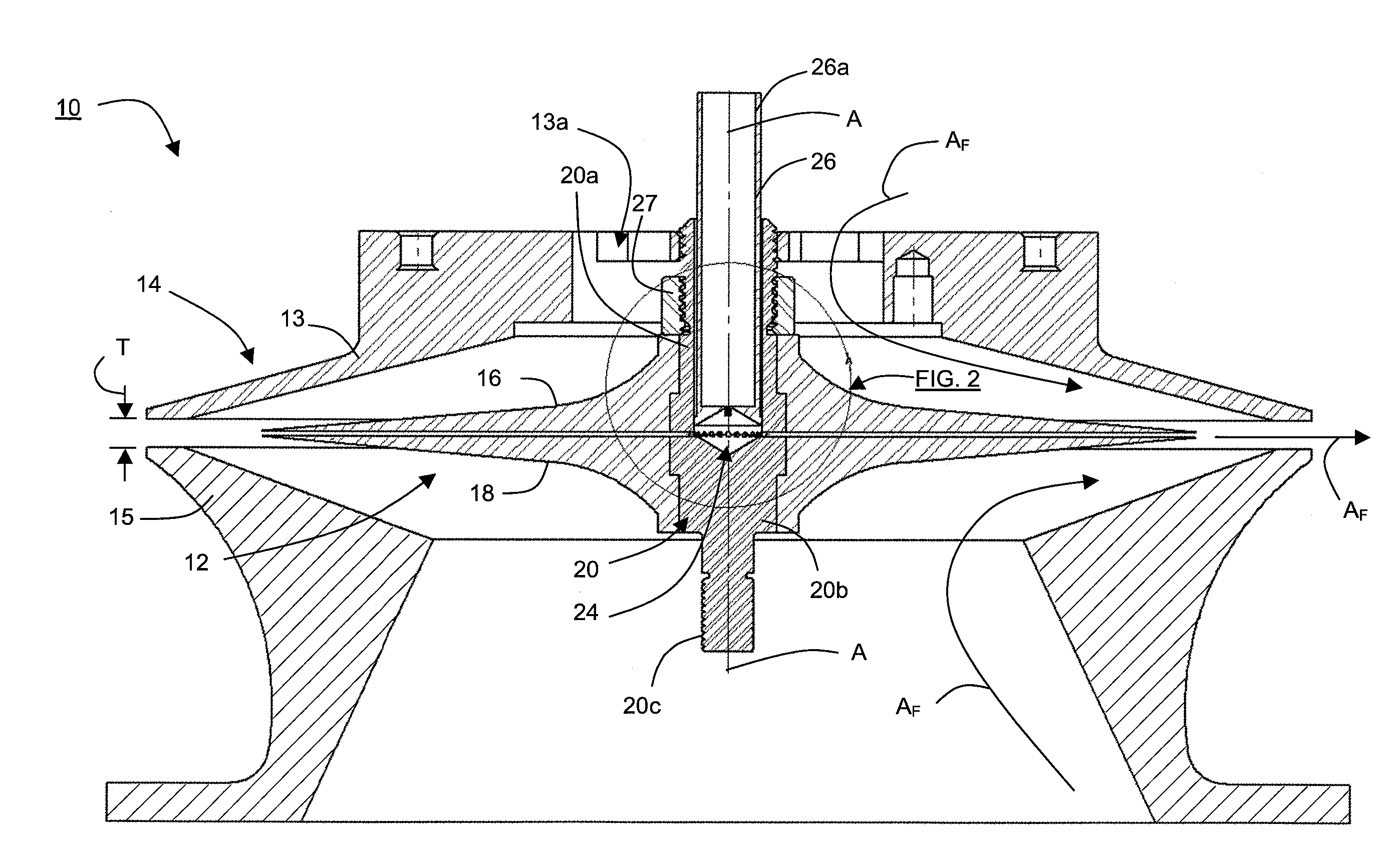
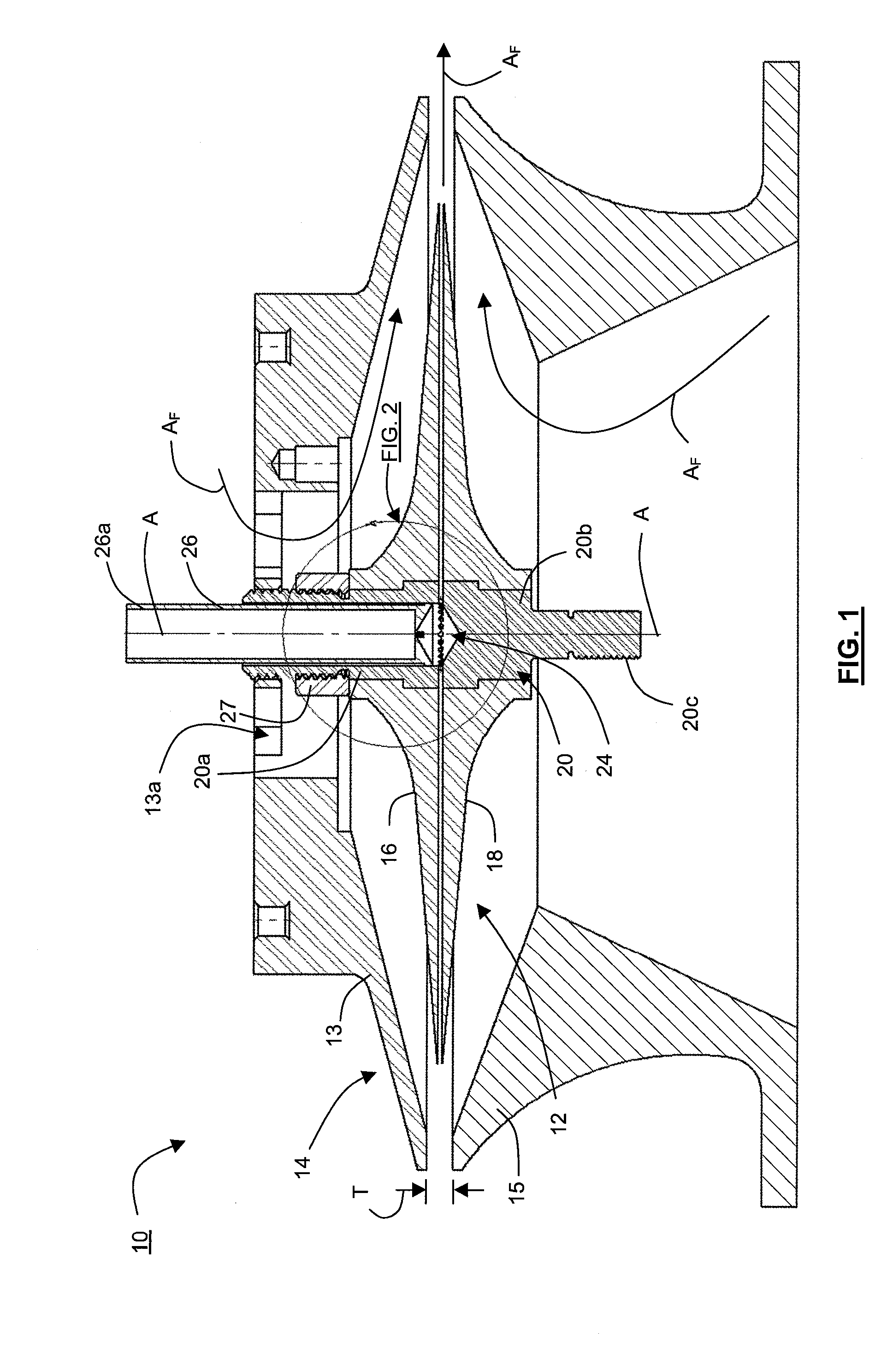
[0063]Turning to FIG. 1, illustrated therein is an apparatus 10 for forming particles according to one embodiment of the invention.

[0064]The term “particles” as generally used herein includes fibers (e.g. filaments, ligaments, etc.), droplets, and other similar shapes made from any suitable liquid (e.g. liquid polymers, molten glasses, molten metals, pure liquids, solutions and suspensions, etc.) and which may solidify, evaporate, and / or remain in liquid form.

[0065]Generally, the apparatus 10 is configured so as to receive the material in a liquid state and then pass the liquid material through one or more rotating capillaries.

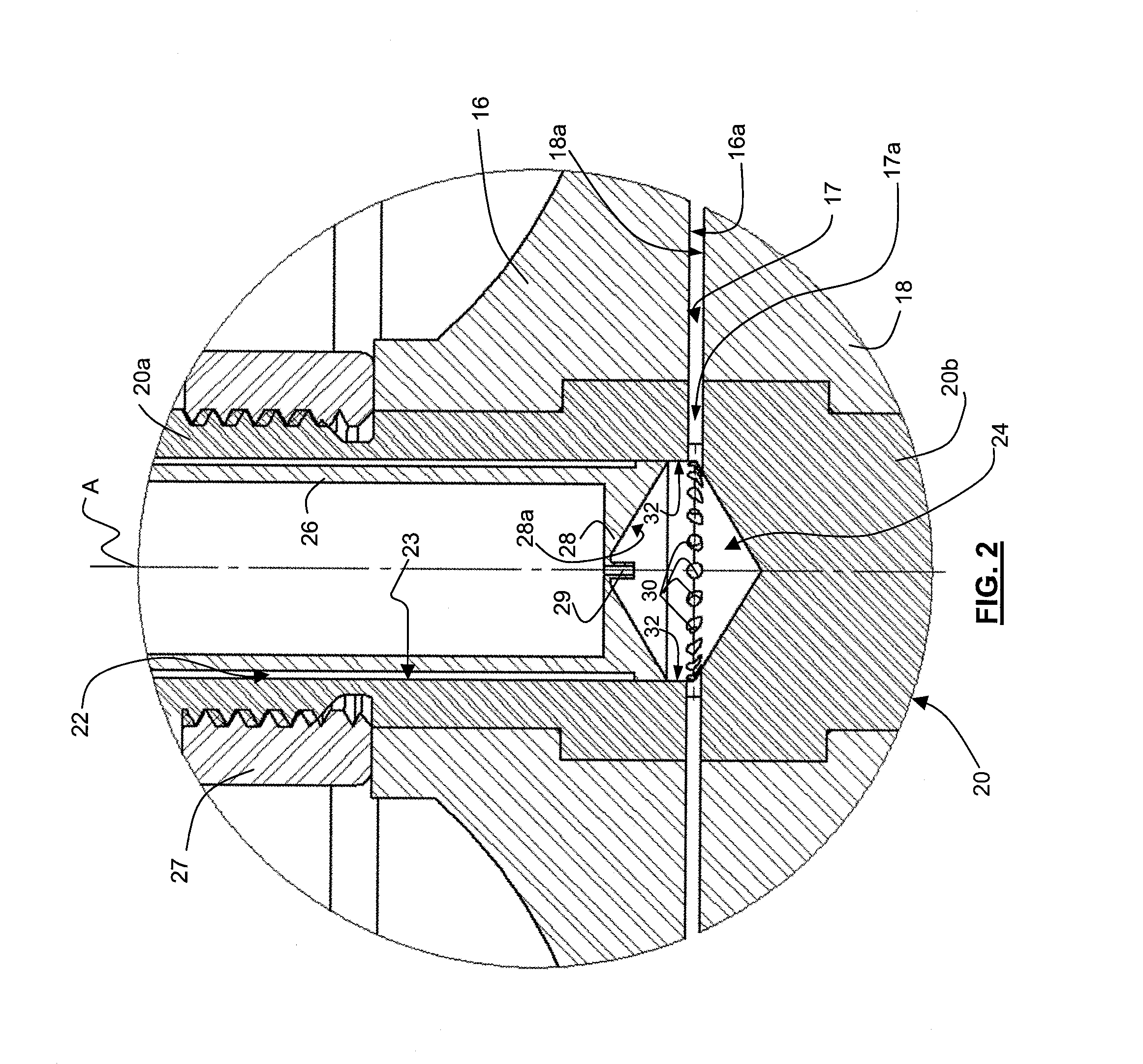
[0066]The term “capillary” as used herein generally refers to a space between two adjacent surfaces, or a space defined within a single surface that is closed in upon itself to present two surfaces that are connected by a curved region (e.g. a capillary tube). For example, the liquid material may be passed through a narrow space between two opposing surfaces o...


PUM

PropertyMeasurementUnit
velocityaaaaaaaaaa
gap distanceaaaaaaaaaa

Abstract

An apparatus for forming particles from a liquid, including a rotor assembly having at least one surface sized and shaped so as to define at least one capillary. Each capillary has an inner region adjacent an axis of rotation of the rotor assembly, an outer region distal from the axis of rotation, and an edge adjacent the outer region. The rotor assembly is configured to be rotated at an angular velocity selected such that when the liquid is received in the inner region of the at least one capillary, the liquid will move from the inner region to the outer region, adopt an unsaturated condition on the at least one surface such that the liquid flows as a film along the at least one surface and does not continuously span the capillary, and, upon reaching the edge, separates from the at least one surface to form at least one particle.

Description

RELATED APPLICATIONS[0001]This application is a continuation-in-part of International Application No. PCT / CA2009 / 000324 filed on Mar. 16, 2009, and entitled “Apparatus, Systems and Methods for Producing Particles Using Rotating Capillaries”, the entire contents of which are hereby incorporated herein by reference for all purposes; this application also claims the benefit of U.S. Provisional Patent Application No. 61 / 235,662 filed on Aug. 20, 2009 and entitled “Apparatus, Systems and Methods for Producing Particles Using Rotating Capillaries”, the entire contents of which are hereby incorporated herein by reference for all purposes; this application also claims the benefit of U.S. Provisional Patent Application No. 61 / 235,670, filed on Aug. 20, 2009 and entitled “Apparatus, Systems and Methods for Producing Particles Using Rotating Capillaries”, the entire contents of which are hereby incorporated herein by reference for all purposes.TECHNICAL FIELD[0002]The embodiments disclosed her...

Claims


Application Information

Patent Timeline
Patent Type & Authority Applications(United States)
IPC IPC(8): B29B9/00B01F25/74
CPCB01F3/0446B01F3/0861B01F5/22D01D5/00C03B37/045D01D5/18C03B19/1015Y02P40/57Y10T428/249921B01F23/232B01F23/45B01F25/74
Inventor KOSLOW, EVAN E.
Owner GABAE TECH
Why Eureka
Try Eureka