Boost-Forward-Flyback High Gain Converter

a high gain converter and forward-flying technology, applied in the field of converters, can solve the problems of complex high gain converters, high cost, and inability to directly apply to renewable energy applications, and achieve the effects of reducing cost, simplifying voltage converting circuits, and improving voltage gain

Inactive Publication Date: 2012-03-08
NAT FORMOSA UNIV
View PDF6 Cites 21 Cited by
  • Summary
  • Abstract
  • Description
  • Claims
  • Application Information

AI Technical Summary

Benefits of technology

[0006]The primary objective of the present invention is to provide a boost-forward-flyback converter to improve voltage gain, decrease cost and simplify the voltage converting circuit.
[0007]A boost-forward-flyback convertor has a boost converting circuit, a forward converting circuit, a flyback converting circuit and a transformer. The boost converting circuit, the forward converting circuit and the flyback converting circuit are coupled by using elements of the boost and forward converting circuits to form the transformer. The boost-forward-flyback convertor combines benefits of conventional boost, forward and flyback convertors, specifically combines active clamping and lower power pressure to the element from the boost convertor, increases gain ratio by using the forward convertor and provides output to the load during a switch OFF-state from the combination of the flyback and boost converting circuit. The boost-forward-flyback convertor combines benefits of conventional boost, forward and flyback convertors and not only has very high gain, high converting efficiency and lower power loading for devices, but also is simple, cost less, easy to use and has a small volume. Other objectives, advantages and novel features of the invention will become more apparent from the following detailed description when taken in conjunction with the accompanying drawings.

Problems solved by technology

Conventional converters are simple, have few elements and cost less, but are not suitable for direct application to renewable energy applications, such as solar cells, wind power, Biofuel or the like, since output voltages of renewable energy applications are usually quite low and the conventional converters do not have enough gain in voltage transformation.
However, compared to the traditional converters, present conventional high gain converters are complex, more expensive, suffer heat generating issues and are very large.

Method used


Image

  • Boost-Forward-Flyback High Gain Converter
  • Boost-Forward-Flyback High Gain Converter
  • Boost-Forward-Flyback High Gain Converter

Examples


Embodiment Construction

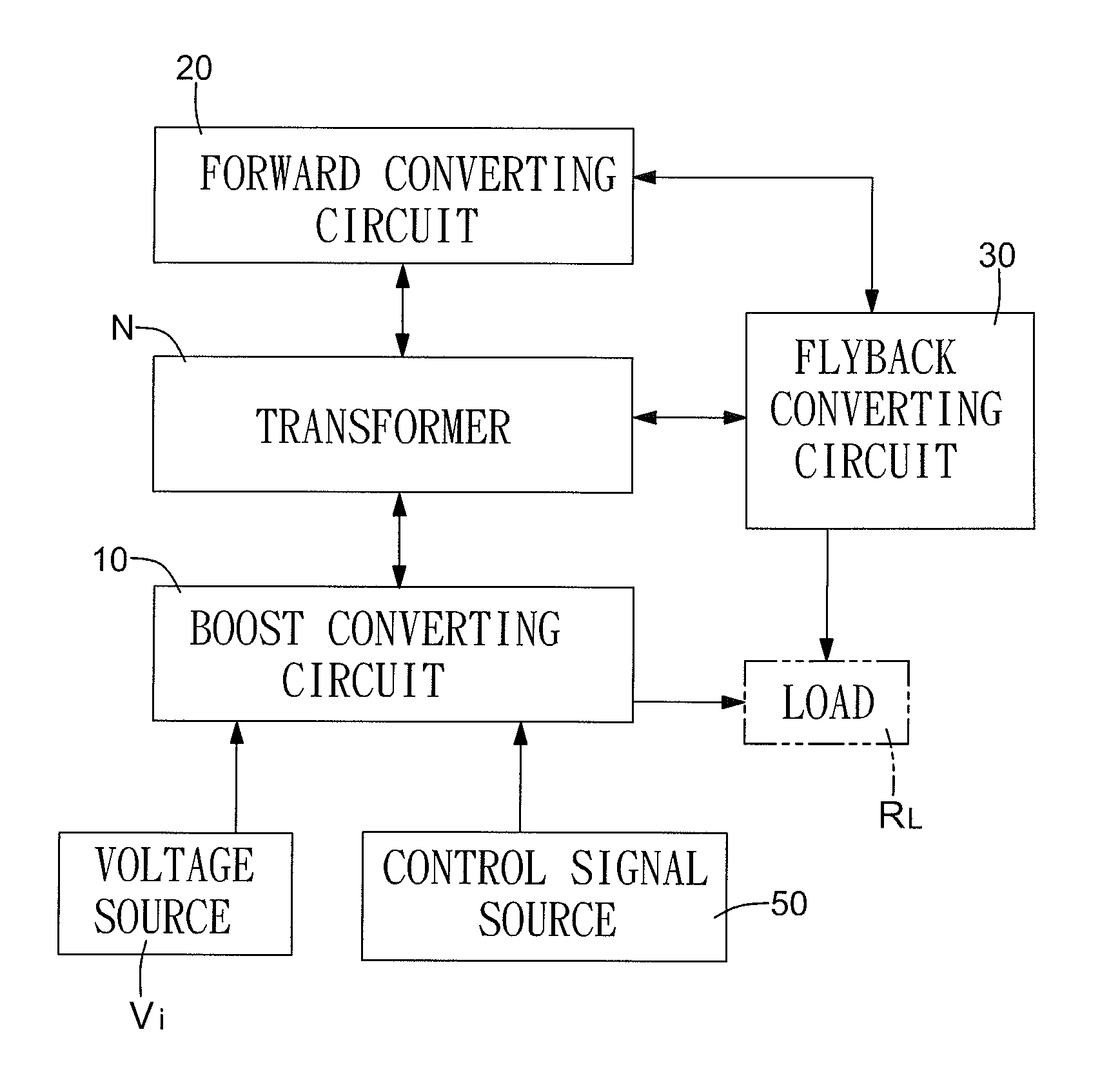
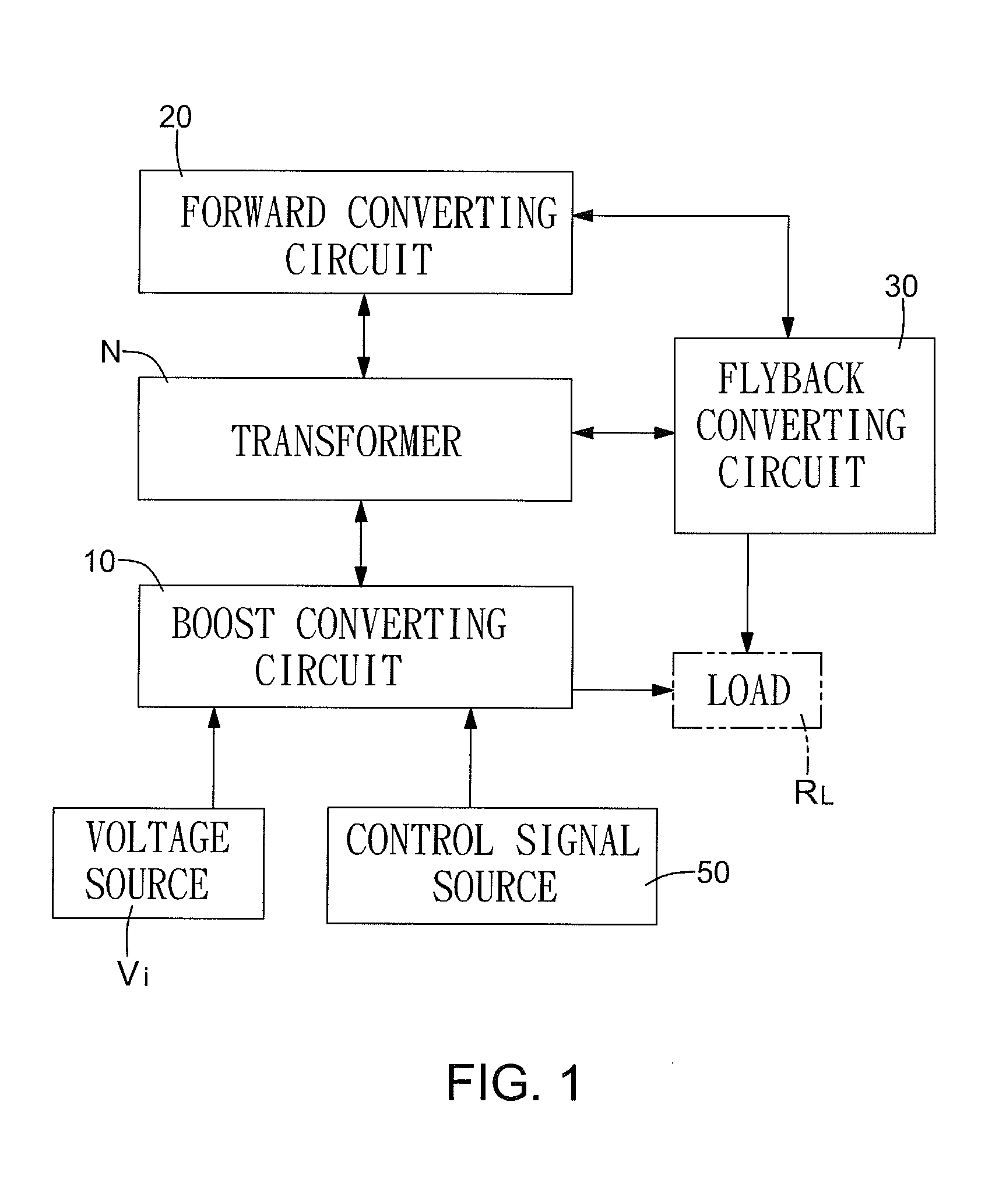
[0023]With reference to FIGS. 1 and 2, a boost-forward-flyback high gain converter in accordance with the present invention comprises a boost converting circuit (10), a forward converting circuit (20), a flyback converting circuit (30) and a transformer (N) and may be implemented in numerous embodiments depending on the implementation of the converting circuits (10, 20, 30) . . . .

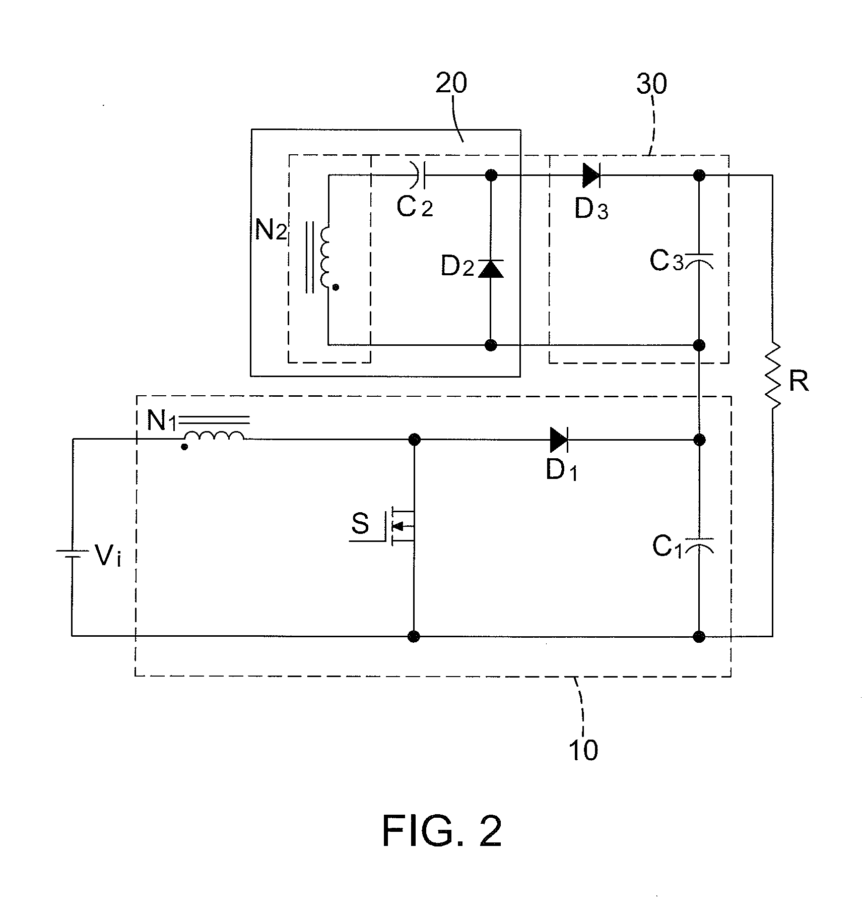
[0024]The boost converting circuit (10) connects to an external voltage source (Vi) and an external control signal source (50) as inputs, is coupled to a load (RL) and comprises a switch (S), an input coil (N1), a boost diode (D1) and a boost capacitor (C1).

[0025]The control signal source (50) sends a control signal to the boost converting circuit (10) to activate voltage conversion between the voltage source (Vi) and the load (RL). The control signal source 50 may be a pulse width modulation (PWM) or the like.

[0026]The switch (S) may be a BJT, FET or the like, is connected to the control signal source (50...


PUM


Abstract

A boost-forward-flyback convertor has a boost converting circuit, a forward converting circuit, a flyback converting circuit and a transformer. The boost converting circuit, the forward converting circuit and the flyback converting circuit are coupled by using elements of the boost and forward converting circuits to form the transformer. The boost-forward-flyback convertor combines benefits of conventional boost, forward and flyback convertors, specifically combines active clamping and lower power pressure to the element from the boost convertor, increases gain ratio by using the forward convertor and provides output to the load during a switch OFF-state from the combination of the flyback and boost converting circuit. The boost-forward-flyback convertor combines benefits of conventional boost, forward and flyback convertors and not only has very high gain, high converting efficiency and lower power loading for devices, but also is simple, cost less, easy to use and has a small volume.

Description

BACKGROUND OF THE INVENTION[0001]1. Field of Invention[0002]The present invention relates to a converter and more particular to a high gain converter with an integrated boost, forward and flyback converting circuit.[0003]2. Description of the Related Art[0004]A converter, also known as a converting circuit, is currently one of the most important circuits for electronic apparatuses. A converter may be an isolated type or a non-isolated type. Typically, the non-isolated type converter comprises a back converter and a boost converter. The isolated type converter comprises half-bridge, full-bridge, push-pull converters, etc. Conventional converters are simple, have few elements and cost less, but are not suitable for direct application to renewable energy applications, such as solar cells, wind power, Biofuel or the like, since output voltages of renewable energy applications are usually quite low and the conventional converters do not have enough gain in voltage transformation. Thus, h...

Claims


Application Information

Patent Timeline
Patent Type & Authority Applications(United States)
IPC IPC(8): H02M3/335H02M3/26
CPCH02M3/155H02M1/34
Inventor LIU, HUAN TSAICHING, TSENG KUOCHOU, PO CHIH
Owner NAT FORMOSA UNIV
Why Eureka
Try Eureka