

Single-tap-inductor Z-source inverter
A source inverter, tapped inductor technology, applied in electrical components, high-efficiency power electronic conversion, conversion of AC power input to DC power output, etc. and other problems, to achieve the effects of suppressing resonant current, large voltage gain, and reducing voltage stress
- Summary
- Abstract
- Description
- Claims
- Application Information
AI Technical Summary
Problems solved by technology
Method used
Image

Examples
specific Embodiment approach 1
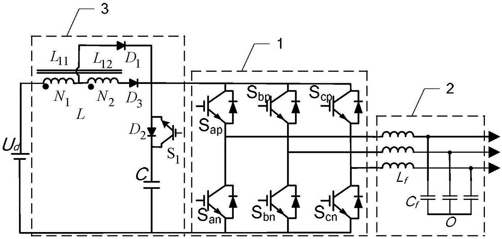
[0029] Specific implementation mode one: the following combination Figure 2-Figure 4 Describe this embodiment, the single-tap inductance Z source inverter described in this embodiment includes a three-phase inverter 1 and an output filter 2, it also includes a single-tap inductance Z source network 3, and the DC power output terminal is connected to a single The input terminal of the tapped inductor Z source network 3, the output terminal of the single-tap inductor Z source network 3 is connected to the input terminal of the three-phase inverter 1, the output terminal of the three-phase inverter 1 is connected to the input terminal of the output filter 2, and the output The output voltage of the output terminal of the filter 2 supplies power for the load;
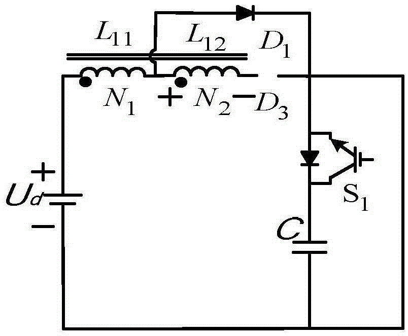
[0030] The single-tap inductor Z source network 3 includes a capacitor C, a tap inductor L, a diode D1, a diode D2, a diode D3 and an insulated gate bipolar transistor S1;
[0031] The positive output terminal of the DC p...
specific Embodiment approach 2
[0033] Specific implementation mode two: the following combination Figure 2-Figure 4 This embodiment will be described. This embodiment will further explain Embodiment 1. The modulation method of the boost control mode of the single-tap inductance Z-source inverter is:
[0034] Setting up a single-tap inductor Z-source inverter involves two states:
[0035] State 1, straight-through state: turn off the insulated gate bipolar transistor S1, so that the upper and lower bridge arms of the three-phase inverter 1 are straight-through, and at this time the single-tap inductor Z source network 3 is disconnected from the three-phase inverter 1 ;
[0036] State 2, non-straight-through state: make the three-phase inverter 1 in the normal working state, turn on the insulated gate bipolar transistor S1, and at this time, the single-tap inductance Z source network 3 and the three-phase inverter 1 provide energy for the load at the same time;
[0037] Set in a switching cycle T, the dura...
specific Embodiment approach 3
[0070] Specific implementation mode three: the following combination Figure 5-Figure 7 This embodiment will be described. This embodiment will further describe the first embodiment. The modulation method of the space vector of the single-tap inductance Z-source inverter is:
[0071] In the modulation method, there are 6 effective voltage vectors, 2 zero voltage vectors and 3 through vectors, among which the 6 effective voltage vectors differ by 60° in turn, and the direction is fixed. The space is divided into six sectors, and the 2 zero voltage vectors are fixed At the origin of the space vector diagram, the three through vectors are generated by the three pairs of bridge arms of the three-phase inverter 1, and the reference vector passes through two adjacent effective voltage vectors U u , U v and the corresponding zero voltage vector U 00 synthesis, through the vector U shoot A boost is achieved where the duty cycles of the two effective voltage vectors are d u and d ...
PUM
 Abstract
Description
Claims
Application Information