
Method and apparatus for rotary molding

a rotary molding and mold cavity technology, applied in the field of molding systems and methods, can solve the problems of entrapped air, difficult to ensure complete and consistent filling of mold cavities, and disadvantages of known prior art mold molding devices, and other problems, to achieve the effect of reducing the speed of high-volume production and eliminating or minimizing disadvantages

Active Publication Date: 2012-03-08
PROVISUR TECHNOLOGIES INC
View PDF7 Cites 63 Cited by
  • Summary
  • Abstract
  • Description
  • Claims
  • Application Information

AI Technical Summary

Benefits of technology

"The present invention provides an improved method and apparatus for molding food patties that overcomes the disadvantages of previous methods without reducing the speed of production. The method involves feeding pressurized food product through a feeder inlet connected to an interface plate, filling mold cavities simultaneously, and providing an outlet for displaced air. The interface plate has perforations to provide the molded food product with the desired texture. A pump accumulator is used to regulate pressure and volume of the food mass in the feed pathway. The mold cavities rotate in a discharge region to remove air and the air discharge region helps to regulate the pressure. The mold cavities are filled from the bottom up and the air discharge region helps to remove air from the mold cavity. The invention also includes a rotary molding system with a feeder portion, fill plate, wear plate, knock-out mechanism, and rotary mold with mold shapes that form mold cavities."

Problems solved by technology

The present inventors have recognized that known prior art molding devices described, and others, have been disadvantageous for various reasons.
The present inventors have recognized that additional problems encountered in high volume food patty molding machines include difficulty in assuring complete and consistent filling of the mold cavity.
The present inventors have recognized that entrapped air also has a tendency to disrupt the ejection process, as the force used to push the formed product out of the mold cavity is not distributed evenly against the molded product.

Method used


Image

  • Method and apparatus for rotary molding
  • Method and apparatus for rotary molding
  • Method and apparatus for rotary molding

Examples


Embodiment Construction

[0113]While this invention is susceptible of embodiment in many different forms, there are shown in the drawings, and will be described herein in detail, specific embodiments thereof with the understanding that the present disclosure is to be considered as an exemplification of the principles of the invention and is not intended to limit the invention to the specific embodiments illustrated.

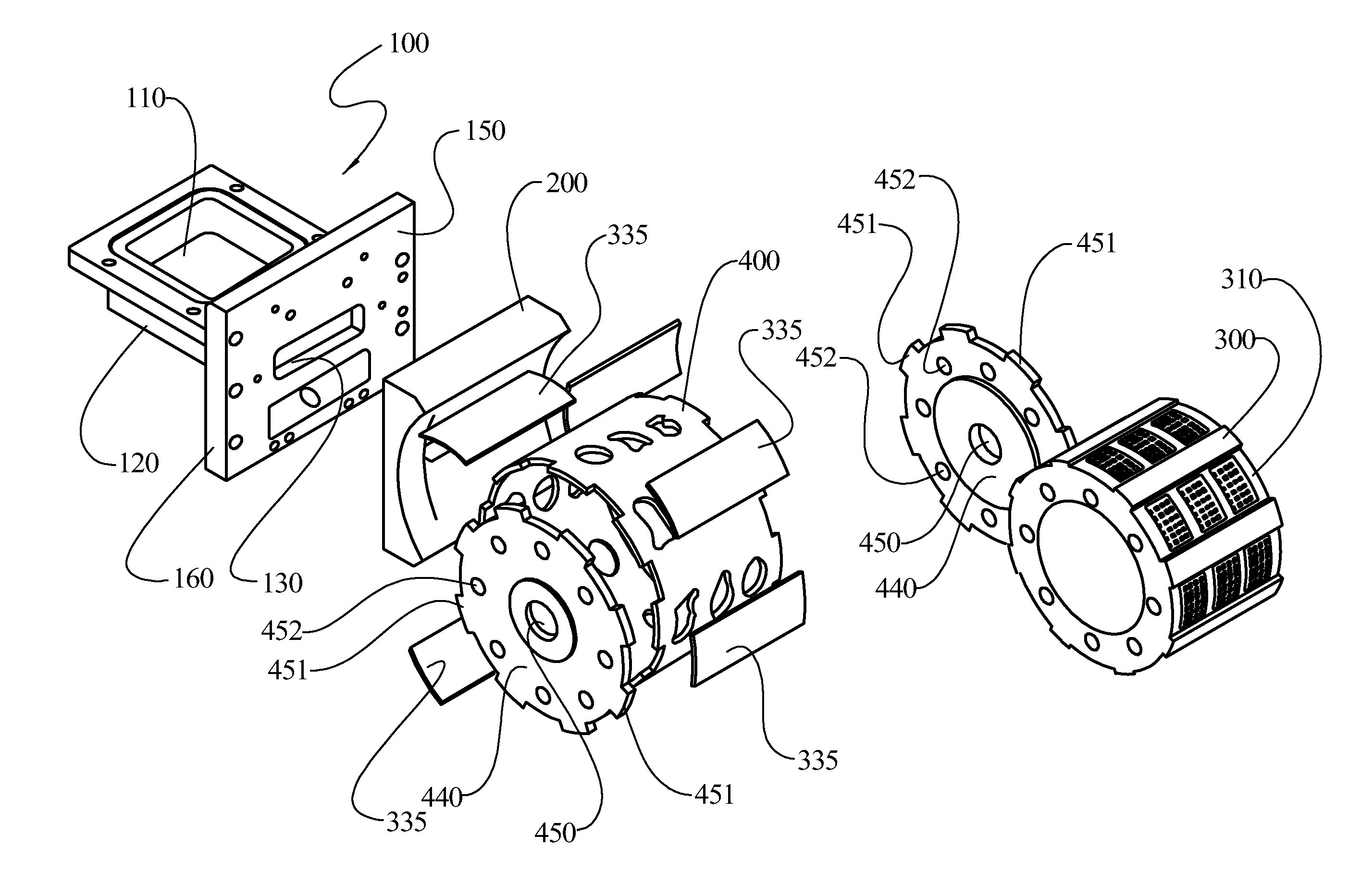
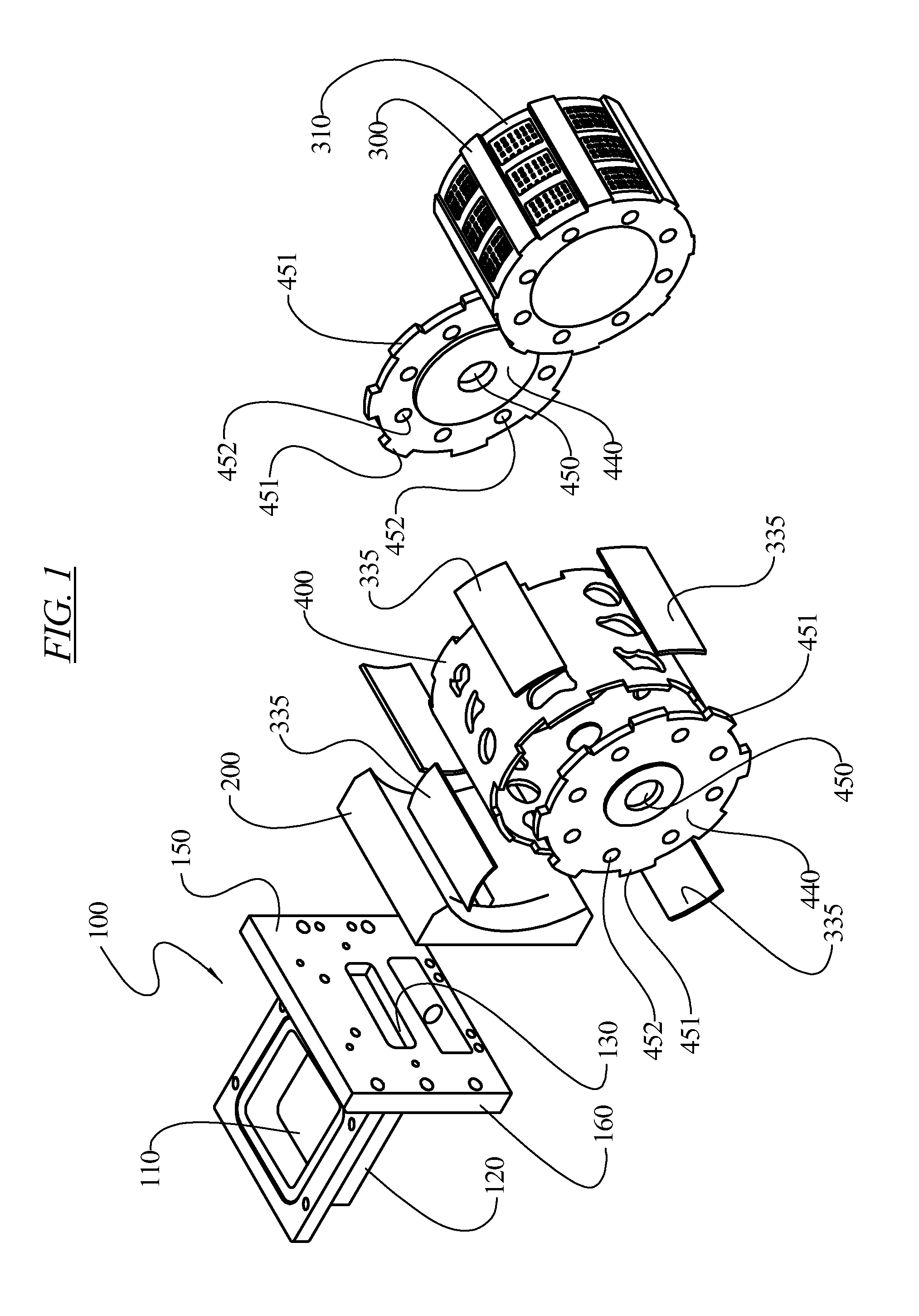
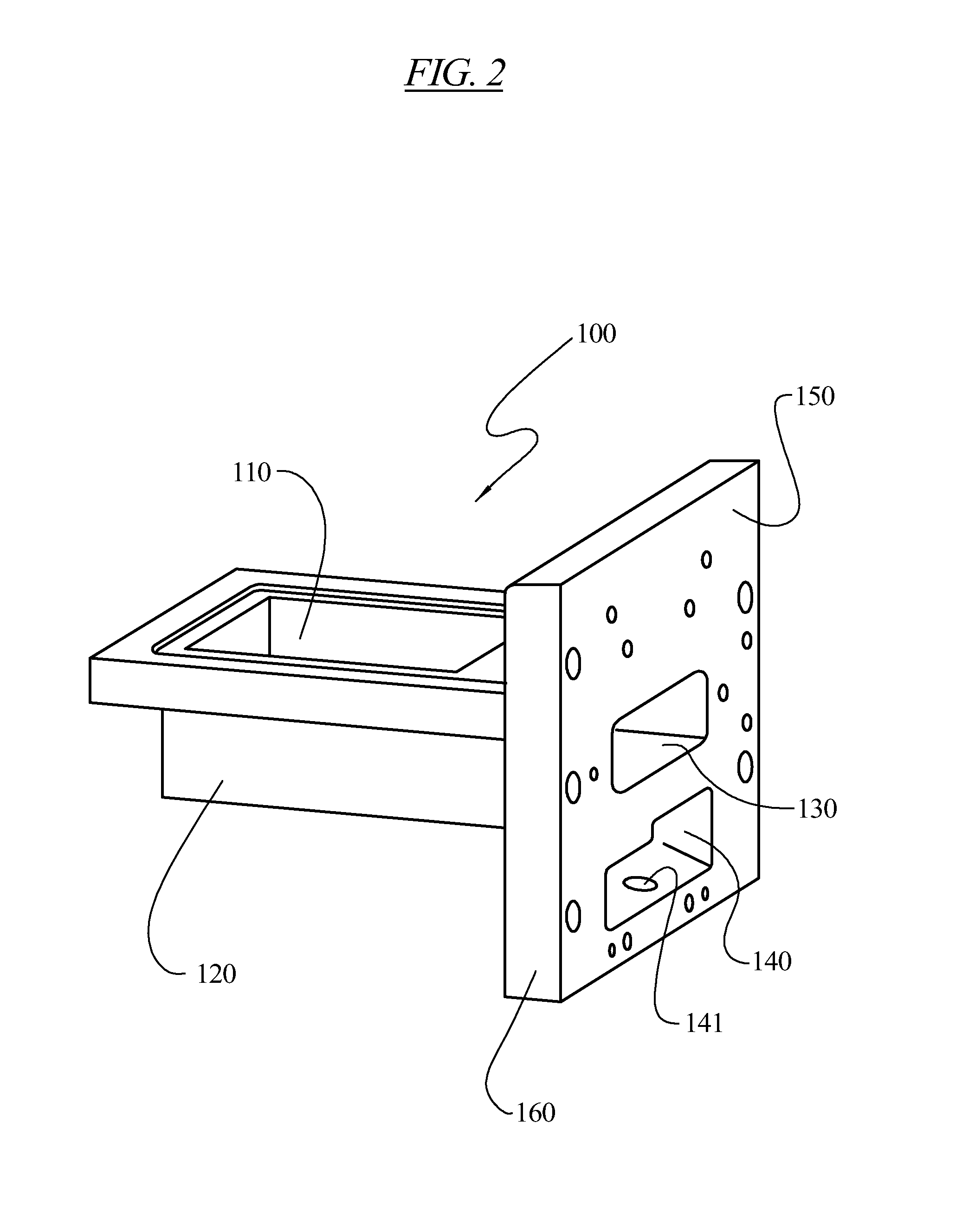
[0114]FIG. 1 illustrates the primary components of an embodiment of a rotary molding system. The rotary molding system comprises a food feeder portion 100, an interface plate 200, a mold cylinder 300, and a mold shell 400. The food feeder portion 100 utilizes a pumping mechanism enclosed in a pump box 120 to feed pressurized food product though the feeder inlet 130 for deposition into the mold cavities. The interface plate 200 adapts the feeder portion 100 to the curvature of the rotary cylinder, which is comprised of the mold cylinder 300 and the mold shell 400.

[0115]The various components of th...


PUM

PropertyMeasurementUnit
angleaaaaaaaaaa
angleaaaaaaaaaa
thicknessaaaaaaaaaa

Abstract

A rotary molding system for molding food products, mold cavities formed when a mold shell rotates mold shapes disposed along the mold shell into a fill position between a fill plate and a wear plate. Molded food products are removed from mold cavities using knock-out cups, the use of air pressure, or the use of a vacuum source disposed below the mold cavity, without the need to slow the rotation of the mold shell. Knock-out cups may be used with a heating system to reduce accumulation of unwanted materials on the knock-out cups. The rotary molding system can also be used to form products with contoured surfaces. A smart tagging system can be used to ensure that compatible sets of mold shells and knock out cups are being used. A vacuum region may be disposed upstream of the fill position to remove air within the mold cavity prior to filling.

Description

[0001]This application claims the benefit of U.S. Provisional Application No. 61,366,033 filed on Jul. 20, 2010.FIELD OF THE INVENTION[0002]This invention relates in general to molding systems and methods for producing specifically shaped products, and more particularly, to the production of food products.BACKGROUND OF THE INVENTION[0003]Food patties of various kinds, including hamburgers, molded steaks, fish cakes, chicken patties, pork patties, potato patties, and others, are frequently formed in high-volume automated molding machines. U.S. Pat. No. 3,851,355 discloses a meat form apparatus of the rotatable wheel type. U.S. Pat. Nos. 3,427,649; 4,212,609 and 4,957,425 disclose methods and machines for producing molded products using a rotary die with porous bottom walls. Patent Application Publication US 2005 / 0220932 discloses methods for molding three dimensional products from food stuffs utilizing porous mold cavities. Patent Application Publication US 2007 / 0224306 also provides...

Claims


Application Information

Patent Timeline
Patent Type & Authority Applications(United States)
IPC IPC(8): B28B7/10B28B7/00A23P1/10
CPCA22C7/0038B29C37/0003A22C7/0092A22C7/0069B30B11/12A22C7/0084B29C45/2725B29C45/4005
Inventor LINDEE, SCOTT A.HANSEN, DAVIDLAMARTINO, SALVATOREBAURE, BRUCEWOLCOTT, THOMAS C.ILL, STEVEWIGHT, E. WILLIAM
Owner PROVISUR TECHNOLOGIES INC
Learn More