System and Method for Monitoring and Controlling Energy System

a technology of energy system and monitoring system, applied in the field of energy systems, can solve the problems of time-consuming, inability to predict the problems that the system may encounter, and inability to identify the problem by data analysis,

Active Publication Date: 2012-03-08
MAHINDRA REVA ELECTRIC VEHICLES PVT
View PDF4 Cites 17 Cited by
  • Summary
  • Abstract
  • Description
  • Claims
  • Application Information

AI Technical Summary

Benefits of technology

[0009]There is also provided a method for adapting control in an energy system which is at least partially powered by electricity. The energy system includes, an energy storage system capable of storing electric energy, an energy consumption system capable of consuming, at least partially, the electric energy stored in the energy storage system, and energy management system comprising instructions for managing the energy storage system and energy consumption system. The method comprises gathering data relating to at least one of the energy storage system and the energy consumption system. The gathered data is used to develop one or more patterns. Further, based on the pattern, it is determined whether modification of the instructions in the energy management system is required. If modification of the instructions in the energy management system is required, then the instructions in the energy management system are modified.

Problems solved by technology

Some of the disadvantages of the above discussed approach of trouble shooting include, consumption of time in either taking the system to a service station or arrival of service personnel at the location of the system.
Further, prediction of problems that the system may encounter may not be possible.
Additionally, the analysis of data to identify the problem may be time consuming.
However, it may be noted that energy system may not always be used under the operating conditions for which the instructions were initially designed.
In such situations, the ESS and the ECS may not deliver optimum performance.

Method used


Image

  • System and Method for Monitoring and Controlling Energy System
  • System and Method for Monitoring and Controlling Energy System
  • System and Method for Monitoring and Controlling Energy System

Examples


Embodiment Construction

[0032]The embodiments disclosed herein and the various features and advantageous details thereof are explained more fully with reference to the non-limiting embodiments that are illustrated in the accompanying drawings and detailed in the following description. Descriptions of well-known components and processing techniques may be omitted so as to not unnecessarily obscure the embodiments disclosed herein. The examples used herein are intended merely to facilitate an understanding of ways in which the embodiments disclosed herein may be practiced and to further enable those of skill in the art to practice the embodiments disclosed herein. Accordingly, the examples should not be construed as limiting the scope of the embodiments disclosed herein.

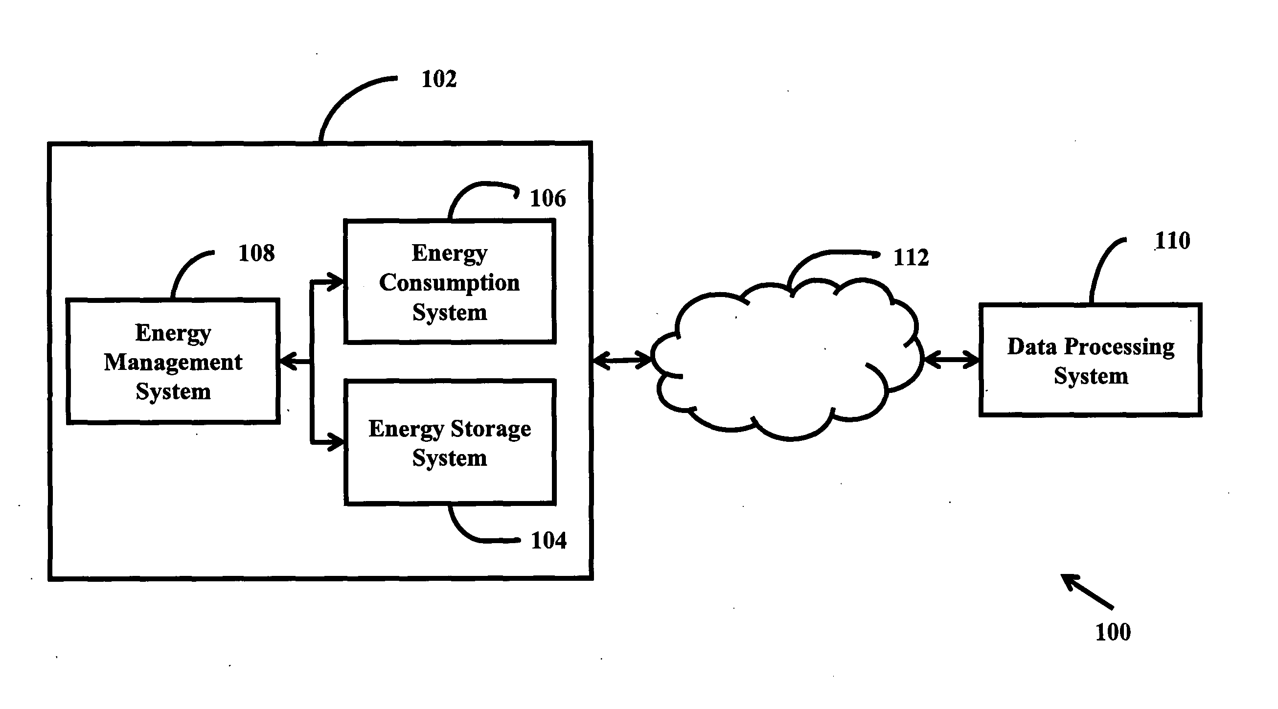
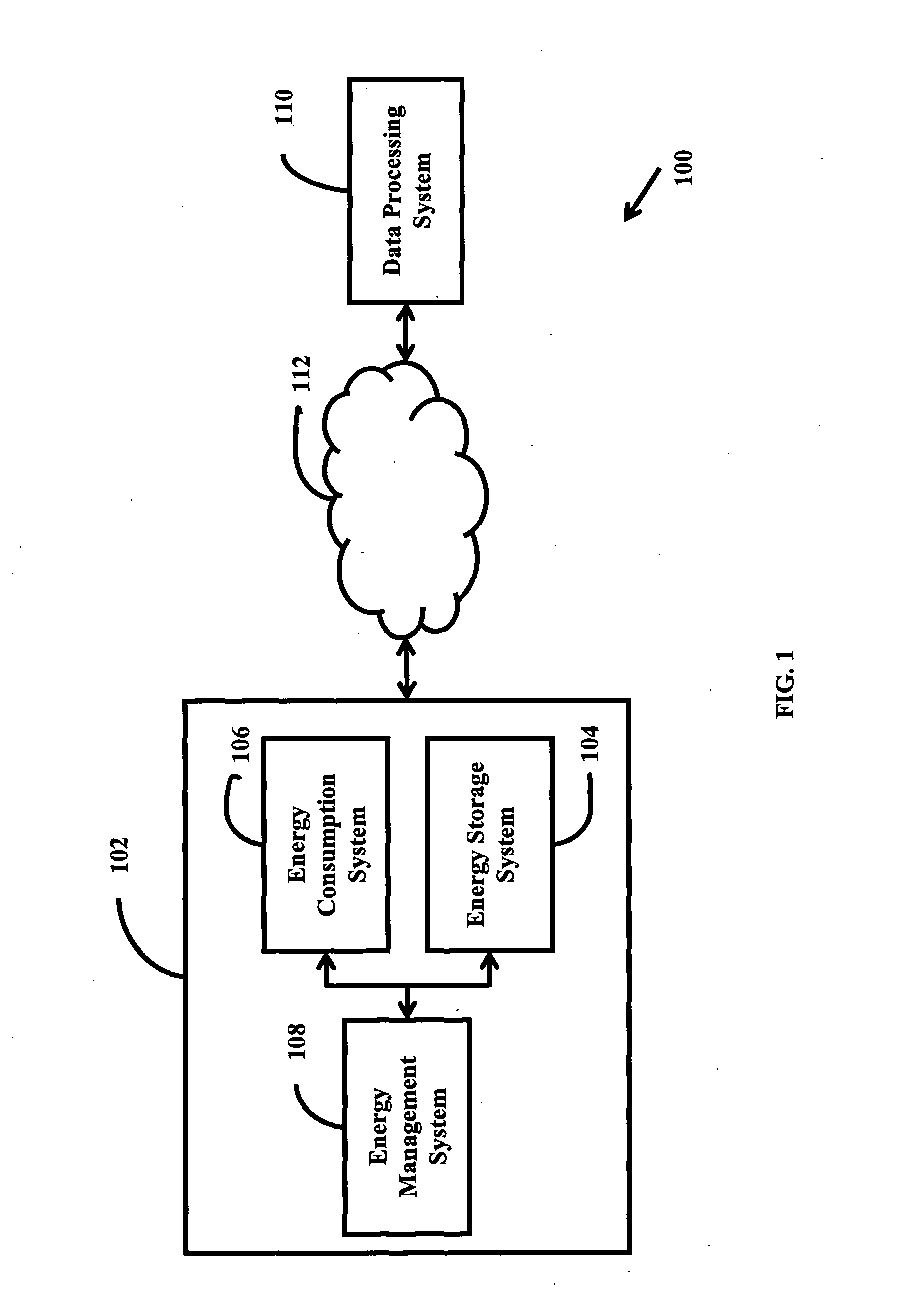
[0033]The embodiments disclosed herein enable identifying at a remote location, at least one condition associated with an energy system. Further, the embodiments disclosed herein enable adapting control in the energy system. Referring now to ...


PUM


Abstract

A method and system for identifying at a remote location provide at least one condition associated with an energy system (102) and control the energy system (102) The energy system (102) includes an energy storage system (ESS) (104) capable of storing electric energy, an energy consumption system (ECS) (106) capable of consuming electric energy from the ESS (104) and an energy management system (EMS) (108) capable of interacting with the ESS (104) and the ECS (106) A parameter associated with the ESS (104) is measured, and the measured parameter is compared with reference data to determine the deviation of the measured parameter from the reference data, and the deviation indicates the condition of the energy system (102) The deviation is determined by the EMS (108) or at the remote location, and the deviation is sent to the remote location while the deviation is determined by the EMS (108).

Description

FIELD[0001]Embodiments generally relate to energy systems which are at least partially powered by electricity, and more particularly but not exclusively, to remote monitoring of energy systems and adapting control in energy systems.BACKGROUND[0002]Examples of energy systems which are at least partially powered by electricity include, but are not limited to, electric vehicles, hybrid electric vehicles and uninterrupted power supply systems. Such energy systems generally include energy storage system (ESS), energy consumption system (ECS) and energy management system (EMS). The ESS is configured to store electric energy that may be consumed by one or more sub-systems of the ECS. Further, the EMS is generally configured to communicate with the ESS and the ECS to manage both, based on the instructions provided in the EMS. The EMS, in addition to being configured to manage both ESS and ECS, is also configured to store data related to various parameters relating to the ESS and ECS that ca...

Claims


Application Information

Patent Timeline
Patent Type & Authority Applications(United States)
IPC IPC(8): G06F1/26
CPCB60L11/1824Y02T90/121B60L2260/54B60R16/03G06Q10/06G06Q30/018G06Q30/02G06Q50/06Y02T10/7005Y02T10/7283Y02T90/12Y02T90/14Y02T90/16Y02T90/169Y04S30/14B60L15/2045Y02T10/72Y02T10/84Y02P90/82Y02T10/64Y02E60/10G01R31/36H01M10/42H01M10/44Y02T10/7072Y02T10/70Y02T90/167
Inventor MAINI, CHETAN KUMARRAMARAJU, PRAKASHSATHYANARAYANA, NAGENDRA BABU
Owner MAHINDRA REVA ELECTRIC VEHICLES PVT
Why Eureka
Try Eureka