
Method and device for operating a drive unit of a motor vehicle

a technology for driving units and motor vehicles, applied in the direction of electric control, speed sensing governors, instruments, etc., can solve the problems of reducing driving comfort, affecting idle speed regulation, and method not contributing to preventing conflict, so as to improve the driving behavior of the motor vehicle, preserve the quality of speed regulation, and improve the driving experien

Inactive Publication Date: 2012-03-08
ROBERT BOSCH GMBH
View PDF7 Cites 9 Cited by
  • Summary
  • Abstract
  • Description
  • Claims
  • Application Information

AI Technical Summary

Benefits of technology

[0007]The method according to the present invention for operating a drive unit of a motor vehicle having the features of claim 1 has the advantage that the quality of the speed regulation is preserved and the drivability of the vehicle is simultaneously made comfortable. Applying the drivability filter before or after the idle speed regulator torque is included in the driver request torque as a function of the instantaneous driving situation of the motor vehicle ensures that either the drivability filter or the idle speed regulator are given greater consideration in operating the drive unit. In this connection, the drivability filter fulfills the task of forming the torque or smoothing its curve in such a way that the vehicle is accelerated without jerking when a switchover is made from idle speed regulation to regulation controlled by the driver which results from the driver's operation of the accelerator pedal. The idle speed regulator fulfills the task of maintaining the idle speed by outputting a suitable torque. The alternating greater consideration of the idle speed regulator or drivability filter results in an improvement of the motor vehicle's driving behavior, in particular in the case of dynamic idle speed regulator interventions. It is possible in this case to check the driving situation using sensors contained per se in the motor vehicle and output it to the control unit, which performs the alternating application of the drivability filter before or after the idle speed regulator torque is included in the driver request torque.
[0008]Advantageously, the idle speed regulator torque is included in different driving torques which occur in a torque path containing the drivability filter. Depending on where the idle speed regulator torque is included in the torque path, in particular added, the output signal of the idle speed regulator or of the drivability filter is given greater or lesser consideration. This makes it possible to make the idle speed regulation including its intervention particularly dynamic.
[0014]One refinement of the exemplary embodiments and / or exemplary methods of the present invention relates to a device for operating a drive unit of a motor vehicle, a setpoint torque being determined for driving the drive unit as a function of a driver request torque and an idle speed regulator torque being included in the driver request torque for determining the setpoint torque and a drivability filter being applied for torque smoothing. In order to maintain the quality of the idle speed regulation when idling and simultaneously prevent a loss of driving comfort, an arrangement provides for applying the drivability filter before or after the inclusion of the idle speed regulator torque into the driver request torque as a function of the instantaneous driving situation. This ensures that the contradictory requirements between the drivability filter, which seeks to form the torque in such a way that the vehicle is accelerated without jerking, and the idle speed regulator, which must maintain the idle speed, are resolved while outputting a suitable torque. This process makes it possible for either the idle speed regulator or the drivability filter to be given greater consideration depending on the driving situation of the motor vehicle.
[0017]In one refinement, a first inclusion point is situated upstream from the drivability filter and a second inclusion point is situated downstream from the drivability filter, at which the idle speed regulator torque predefined by the idle speed regulator may be included. A switching element is also provided. Switching over the switching element makes it possible to activate very rapidly the inclusion points at which the idle speed regulator torque predefined by the idle speed regulator is included upstream or downstream from the drivability filter. The consequence of this is that a high dynamic is ensured in the case of idle speed regulator interventions.

Problems solved by technology

During idling, the functions of the idle speed regulator and of the drivability filter result in a contradiction, since the idle speed regulator wants to build up the idle speed regulator torque rapidly.
If this is done, Bonanza effects occur on the drive shaft of the vehicle, which results in reduction of driving comfort.
This has, however, the disadvantage of impairing the idle speed regulation, since the drivability filter causes a phase shift in the control loop.
However, this method does not contribute to preventing the conflict described above in the case of dynamic idle speed regulator interventions.

Method used


Image

  • Method and device for operating a drive unit of a motor vehicle
  • Method and device for operating a drive unit of a motor vehicle
  • Method and device for operating a drive unit of a motor vehicle

Examples


Embodiment Construction

[0024]Identical features are denoted by identical reference numbers.

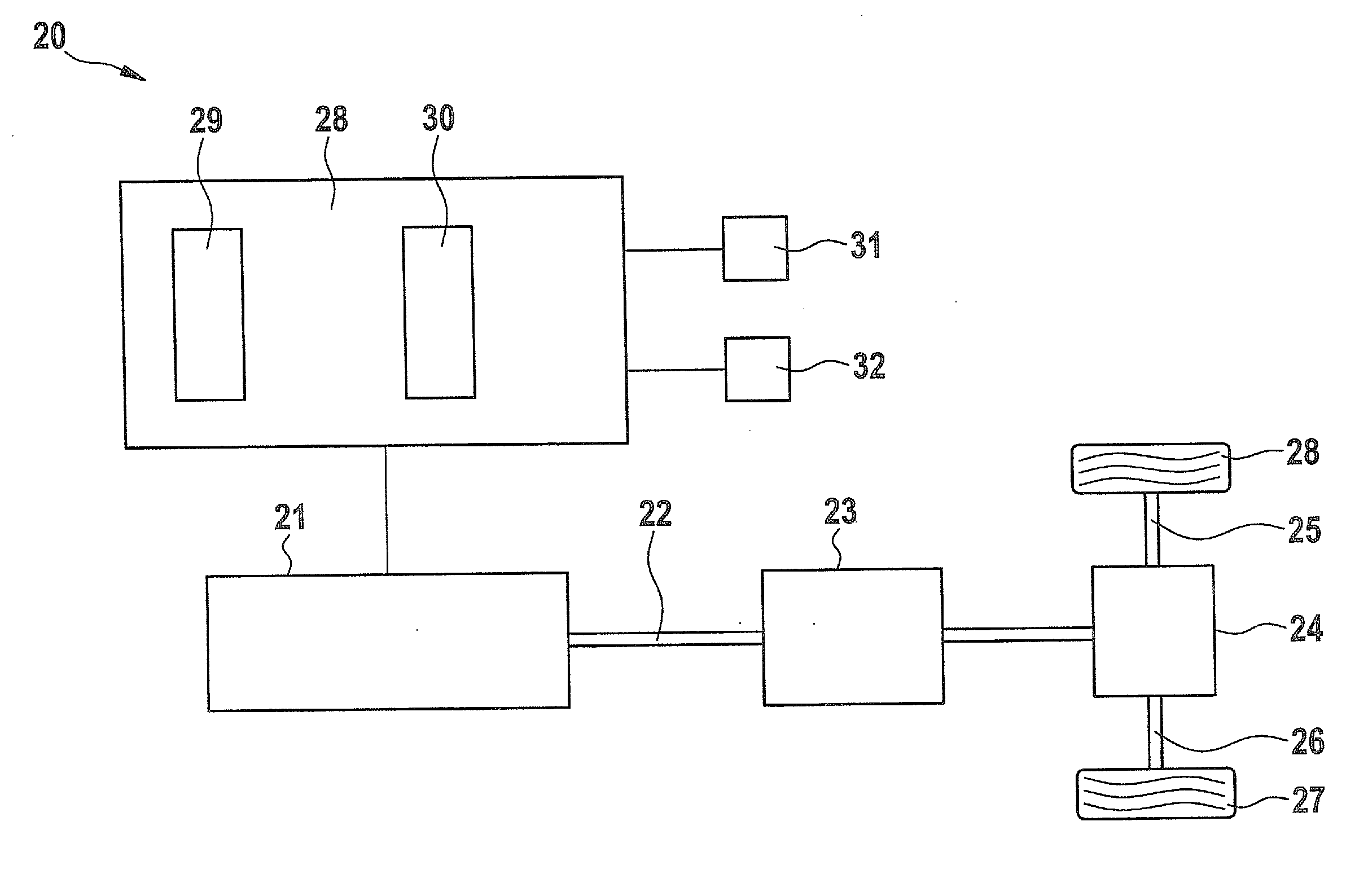
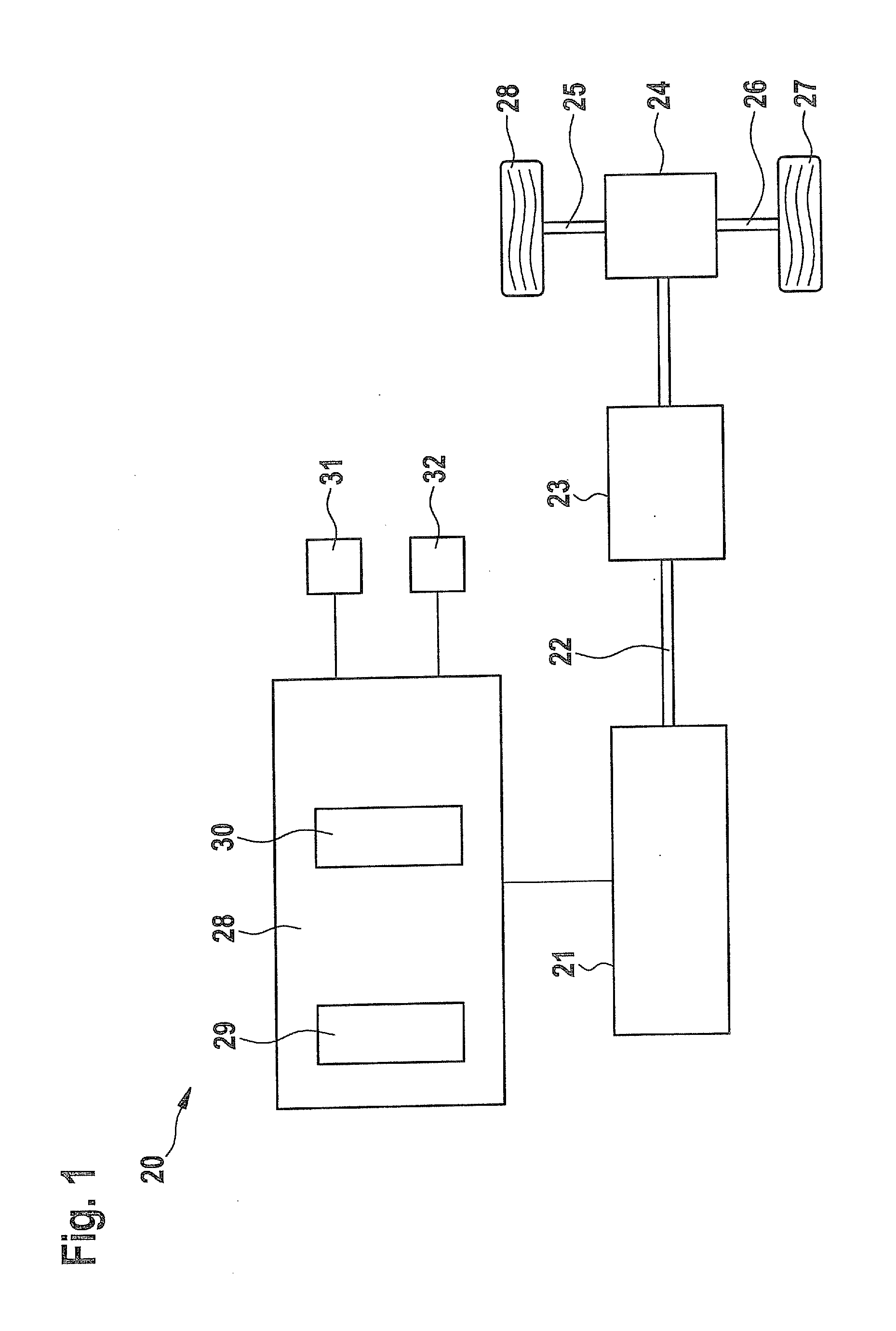
[0025]A schematic diagram of a drive unit 20 of a motor vehicle is represented in FIG. 1. Drive unit 20 includes an internal combustion engine 21 which is connected to a transmission 23 via a drive shaft 22. Transmission 23 leads to a differential 24 which is situated on a vehicle axle 25. Two drive wheels 26 and 27 are positioned on vehicle axle 25. Internal combustion engine 21 is activated by an engine control unit 28. Engine control unit 28 includes, for example, an idle speed regulator 29 and a drivability filter 30. Numerous sensors lead to engine control unit 28, of which only an accelerator pedal sensor 31 and an engine speed sensor 32 are represented.

[0026]Idle speed regulator 29 represents the regulation of a speed of drive unit 20 in the idling state, i.e., in the state in which no driver request is present and the driver does not operate the accelerator pedal. Drivability filter 30 filters the driver req...


PUM


Abstract

A method is described for operating a drive unit of a motor vehicle, a setpoint torque being determined for driving the drive unit as a function of a driver request torque and an idle speed regulator torque being included in the driver request torque for determining the setpoint torque, and a drivability filter being applied for torque smoothing. In order to maintain the quality of the speed regulation and simultaneously make the drivability of the vehicle comfortable, the drivability filter is applied before or after the inclusion of the idle speed regulator torque in the driver request torque as a function of the instantaneous driving situation of the motor vehicle.

Description

RELATED APPLICATION INFORMATION[0001]The present application claims priority to and the benefit of German patent application no. 10 2010 040 279.6, which was filed in Germany on Sep. 6, 2010, the disclosure of which is incorporated herein by reference.FIELD OF THE INVENTION[0002]The present invention relates to a method for operating a drive unit of a motor vehicle, a setpoint torque being determined for driving the drive unit as a function of a driver request torque and an idle speed regulator torque being included in the driver request torque for determining the setpoint torque and a drivability filter being applied for torque smoothing, as well as a device for implementing the method.BACKGROUND INFORMATION[0003]In the case of motor vehicles having an internal combustion engine, a so-called idle speed regulation is used. This idle speed regulation has the task of keeping the internal combustion engine at a so-called idle speed when a torque request from the driver is absent or too...

Claims


Application Information

Patent Timeline
IPC IPC(8): F02D28/00
CPCF02D11/105F02D31/003F02D2250/21F02D41/16F02D2041/1432F02D31/008
Inventor SEEL, ANDREAS
Owner ROBERT BOSCH GMBH
Learn More