Single piece packer extrusion limiter ring

a limiter ring and single-piece technology, applied in the field of downhole tools, can solve the problems of complicated and expensive, unusable extrusion of packer elements,

Active Publication Date: 2012-03-15
HALLIBURTON ENERGY SERVICES INC
View PDF3 Cites 87 Cited by
  • Summary
  • Abstract
  • Description
  • Claims
  • Application Information

AI Technical Summary

Benefits of technology

[0009]In an embodiment, a downhole tool is disclosed. The downhole tool comprises a mandrel, a packing element carried on the mandrel, and an extrusion limiting assembly carried on the mandrel and proximate the packing element. The extrusion limiting assembly comprises a plurality of separate segments and an elastomeric cover that is one of molded circumferentially over or coated circumferentially over the segments. In an embodiment, the elastomeric cover mitigates extrusion of the packing element through gaps between the segments in a set condition of the downhole tool. In an embodiment, the elastomeric cover is from about 0.010 inches thick to about 0.090 inches thick. In an embodiment, the segments are comprised of at least one of epoxy material, phenolic material, and other thermoset material. In an embodiment, the segments number inclusively from four segments to sixteen segments. In an embodiment, the cover is one of silicone, Nitrile, HNBR, fluoroelastomer, silicon rubber, nitrile rubber, or other material. In an embodiment, the downhole tool further comprises an end component carried on the mandrel at a downhole end of the tool, wherein the end component is comprised of a drillable material and defines a first notch in a downhole edge of the end component, wherein the width of the first notch is at least ten percent and less than forty percent of the circumference of the downhole edge and the depth of the first notch is at least ten percent of the length of the end component.
[0010]In an embodiment, a downhole tool is disclosed. The downhole tool comprises a mandrel, a packing element carried on the mandrel, and an end component carried on the mandrel at a downhole end of the tool. The end component is comprised of a drillable material and defines a first notch in a downhole edge of the end component, wherein the width of the first notch is at least ten percent and less than forty percent of the circumference of the downhole edge and the depth of the first notch is at least ten percent of the length of the end component. In an embodiment, the end component further defines a second notch in the downhole edge of the end component, wherein a center of the second notch is about 180 degrees circumferentially away from a center of the first notch. In an embodiment, the end component defines a cylindrical shell and the mandrel extends partially into an uphole end of the end component, and the end component further comprises a pin held by two holes in a wall of a downhole end of the end component without passing through the mandrel. In an embodiment, the end component defines a cylindrical shell, an uphole end of the cylindrical shell has a first outside diameter, and a downhole end of the cylindrical shell has a second outside diameter, wherein the first outside diameter is greater than the second outside diameter. In an embodiment, the uphole end of the cylindrical shell has a first inside diameter and the downhole end of the cylindrical shell has a second inside diameter, wherein the first inside diameter is less than the second inside diameter. In an embodiment, the outer circumferential side of the cylindrical downhole edge is beveled. In an embodiment, the end component further comprises a ceramic insert coupled to an inside of a downhole end of the end component. In an embodiment, the downhole tool further comprises an extrusion limiting assembly carried on the mandrel and proximate the packing element, wherein the extrusion limiting assembly comprises a plurality of separate segments and an elastomeric band that substantially covers an outer circumferential surface of the separate segments.

Problems solved by technology

The shoes are typically segmented and, when the tool is set in a well, spaces between the expanded segments have been found to allow undesirable extrusion of the packer elements, at least in high pressure and high temperature wells.
Numerous improvements have been made in efforts to prevent the extrusion of the packer elements, and while some have been effective to some extent, they have been complicated and expensive.

Method used


Image

  • Single piece packer extrusion limiter ring
  • Single piece packer extrusion limiter ring
  • Single piece packer extrusion limiter ring

Examples


examples

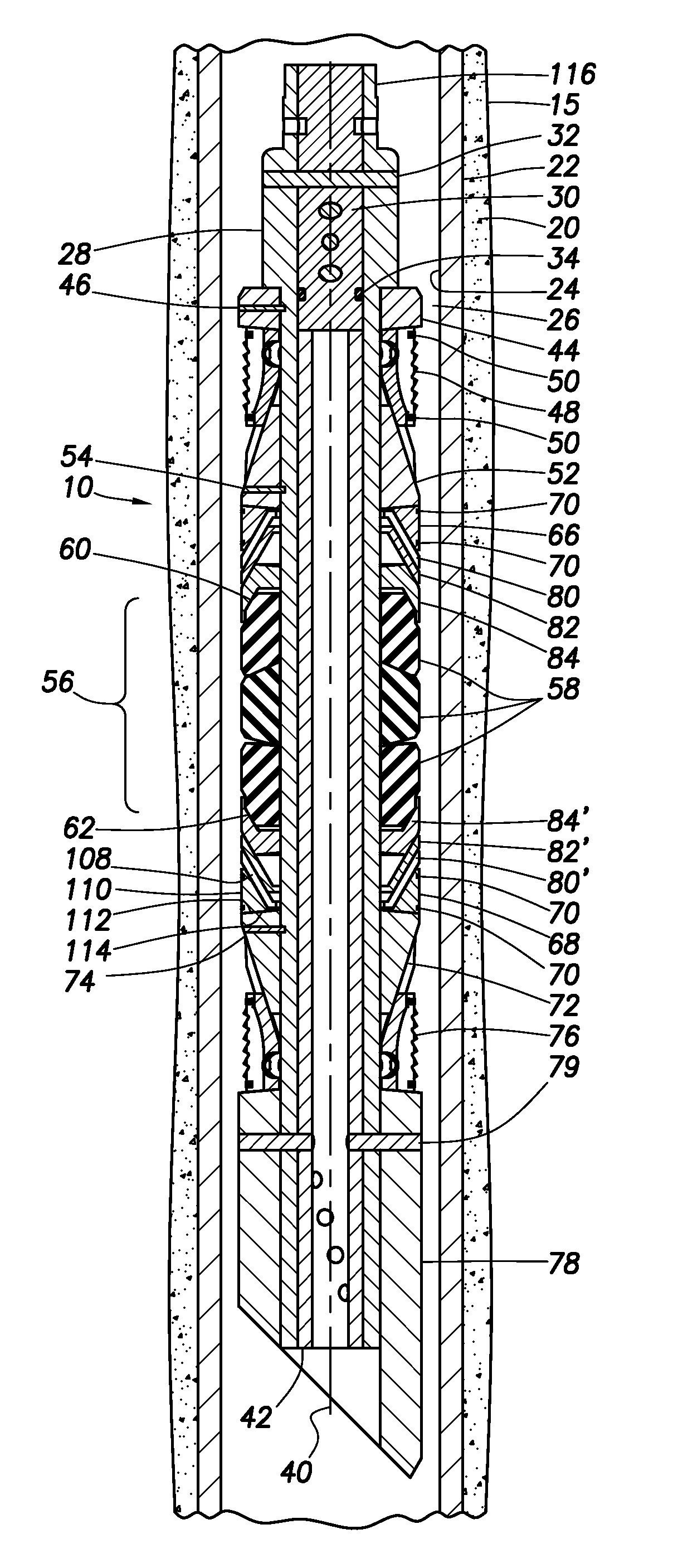
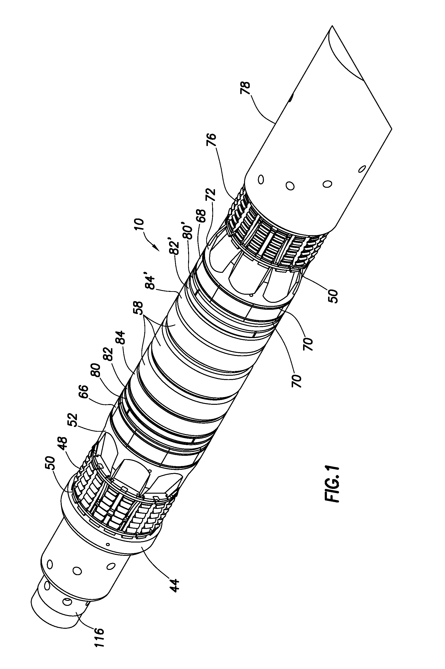
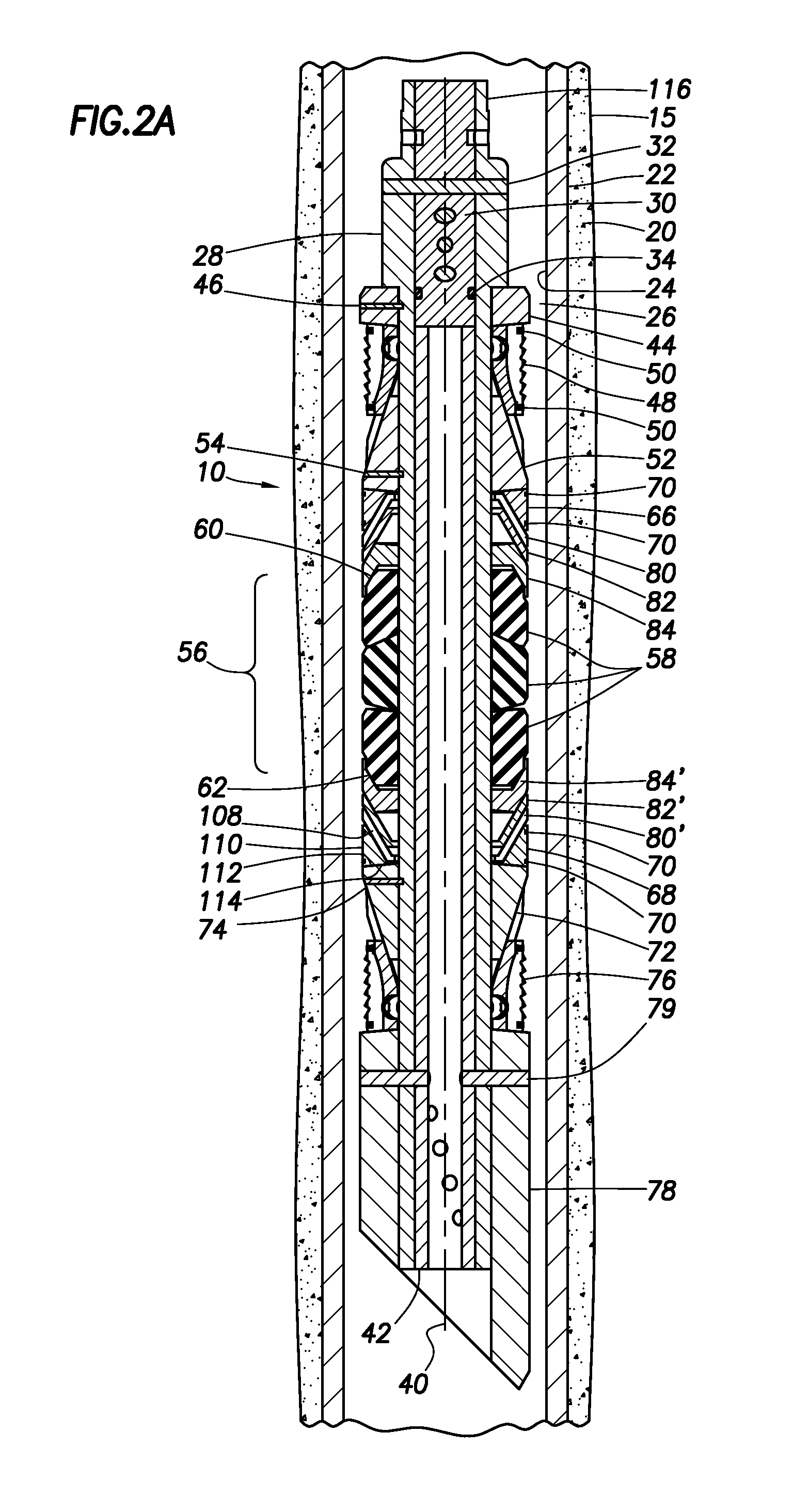
[0066]Two different embodiments of the expandable band 140 described above were fabricated and tested. Five expandable bands 140 for use with the segmented backup shoe 66, 68 having a 5½ inch outside diameter were fabricated of 70 Durometer Nitrile Rubber, and five expandable bands 140 for use with the segmented backup shoe 66, 68 having a 5½ inch outside diameter were fabricated of 60 Durometer Silicone Rubber. Prior to testing, all parts were heated to about 325 degree Fahrenheit.

[0067]In a first test, the outer surface of the segmented backup shoe 66, 68 was abraded for bond to rubber, two retaining bands 70 were disposed within circumferential grooves 71, a first 70 Durometer Nitrile Rubber expandable band 140 was fitted over the segmented backup shoe 66, 68, and a release agent was applied over the expandable band 140 to prevent rubber bond. When about 650 pounds force was applied to the packer including the segmented backup shoe 66, 68 and the expandable band 140, the packer e...


PUM


Abstract

An apparatus for use in a wellbore is provided. The apparatus comprises a mandrel, a sealing element carried on the mandrel, the sealing element being radially expandable from a first run-in diameter to a second set diameter in response to application of axial force on the sealing element, and an extrusion limiting assembly carried on the mandrel and proximate the sealing element. The extrusion limiting assembly comprises a plurality of separate segments and a first circumferential band that retains the plurality of segments in a ring shape and substantially covers an outer circumferential surface of the plurality of segments while in a run-in condition of the apparatus.

Description

CROSS-REFERENCE TO RELATED APPLICATIONS[0001]None.STATEMENT REGARDING FEDERALLY SPONSORED RESEARCH OR DEVELOPMENT[0002]Not applicable.REFERENCE TO A MICROFICHE APPENDIX[0003]Not applicable.BACKGROUND OF THE INVENTION[0004]In the drilling or reworking of oil wells, a great variety of downhole tools are used. For example, but not by way of limitation, it is often desirable to seal tubing or other pipe in the casing of the well, such as when it is desired to pump cement or other slurry down the tubing and force the cement or slurry around the annulus of the tubing or out into a formation. It then becomes necessary to seal the tubing with respect to the well casing and to prevent the fluid pressure of the slurry from lifting the tubing out of the well or for otherwise isolating specific zones in a well. Downhole tools referred to as packers and bridge plugs are designed for these general purposes and are well known in the art of producing oil and gas.[0005]When it is desired to remove m...

Claims


Application Information

Patent Timeline
Patent Type & Authority Applications(United States)
IPC IPC(8): E21B33/12
CPCE21B33/128E21B33/1216
Inventor NEER, ADAM K.HAVELKA, EMILCROCKFORD, LLOYD
Owner HALLIBURTON ENERGY SERVICES INC
Why Eureka
Try Eureka