Coupling structure for resonant gyroscope

a gyroscope and coupling structure technology, applied in the field ofinertial sensors, can solve the problems of difficult manufacture of a gyroscope for a detection in axis z, structure remains sensitive to parasitic modes outside the plane, and cannot enable displacement amplitude adjustmen

Active Publication Date: 2012-03-15
COMMISSARIAT A LENERGIE ATOMIQUE ET AUX ENERGIES ALTERNATIVES
View PDF25 Cites 39 Cited by
  • Summary
  • Abstract
  • Description
  • Claims
  • Application Information

AI Technical Summary

Benefits of technology

[0026]The coupling structure may, in order to impart vibration to at least four seismic masses under the effect of four excitation means, include four closed patterns, where the closed patterns are connected by one of their peaks at a point constituting the centre of symmetry of the coupling structure, so as to present patterns which are opposite and aligned two-by-two, with two opposite and aligned patterns being orthogonal to the other two opposite and aligned patterns, and where two consecutive patterns are each intended to be connected by a beam to one of the said masses, such that two opposite seismic masses are located on the same axis passing through the centre of symmetry. The peaks of the patterns opposite the centre of symmetry of the coupling structure may each be coupled securely to an excitation means. The other two seismic masses may be mutually orthogonal, and offset by 45° relative to the opposite and aligned patterns.

Problems solved by technology

However, the structure remains sensitive to parasitic modes outside the plane.
However, these structures do not enable the displacement amplitudes to be adjusted.
This configuration makes manufacture of a gyroscope for a detection in axis z quite difficult.

Method used


Image

  • Coupling structure for resonant gyroscope
  • Coupling structure for resonant gyroscope
  • Coupling structure for resonant gyroscope

Examples


Embodiment Construction

[0029]The invention will be better understood and other advantages and features will appear on reading the following description, which is given as a non-restrictive example, accompanied by the appended illustrations, among which:

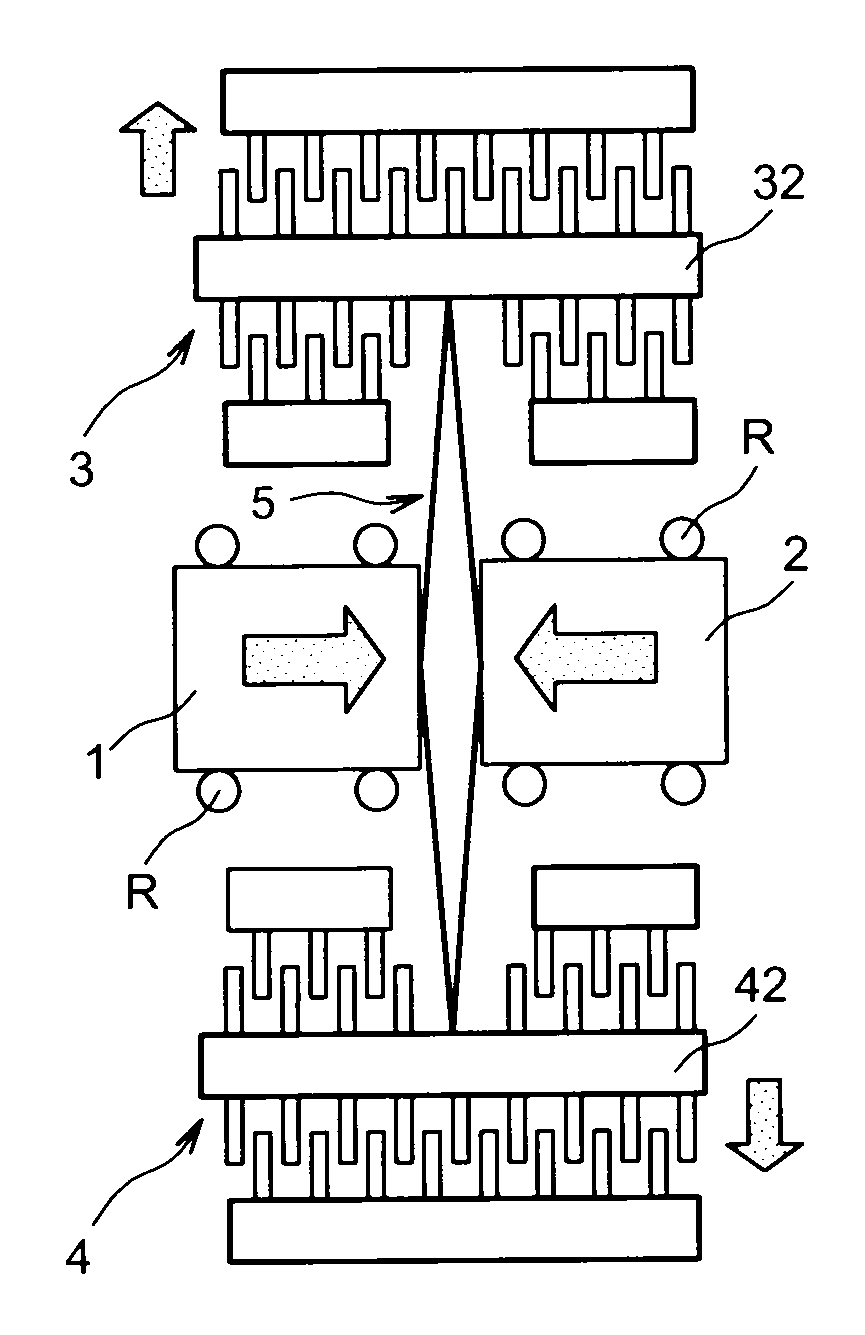
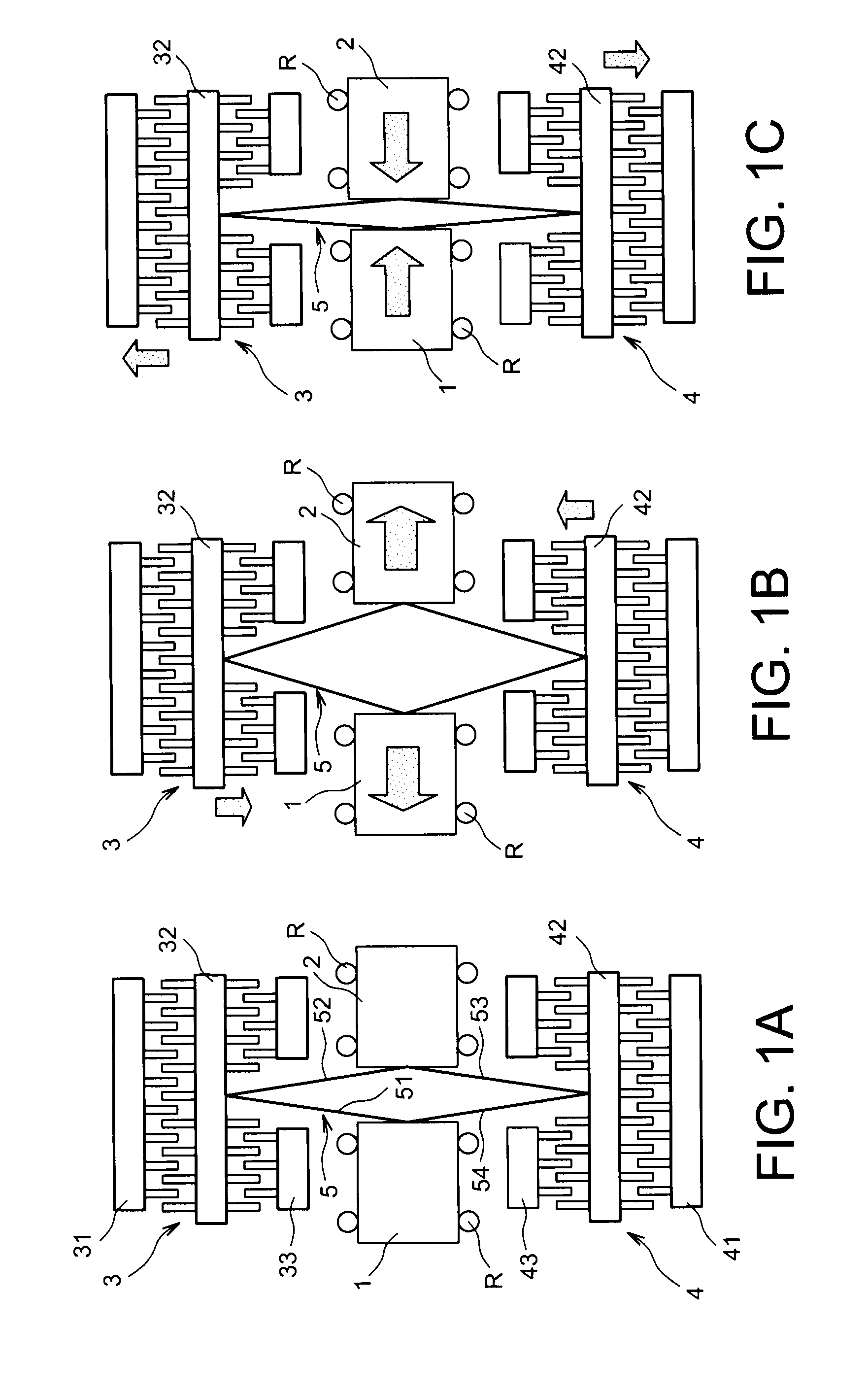
[0030]FIGS. 1A to 1C are schematic diagrams of a one-axis resonant gyroscope according to the present invention,

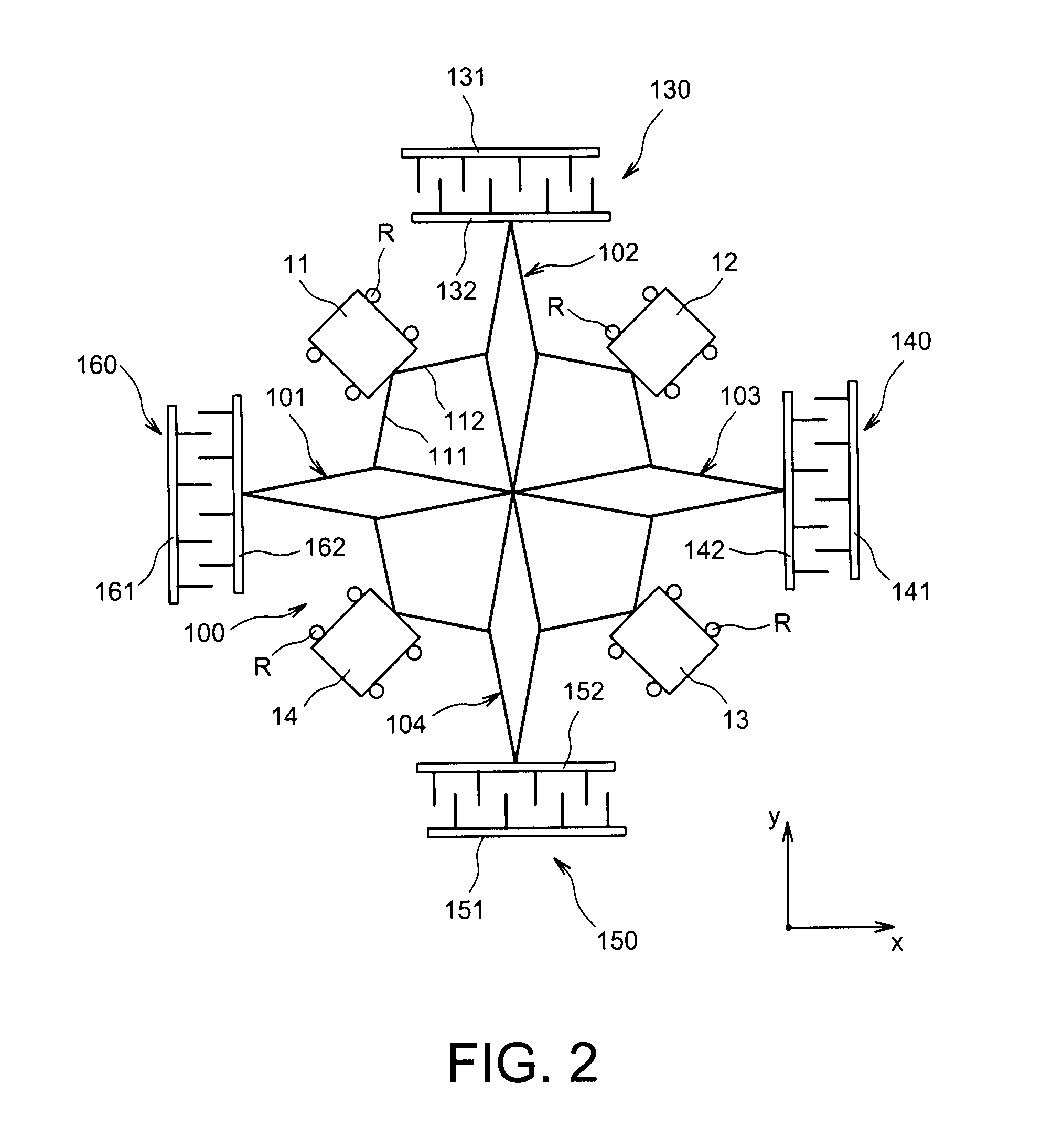
[0031]FIG. 2 is a schematic diagram of a two-axis resonant gyroscope, with antiphase coupling with amplified displacement amplitude, according to the invention,

[0032]FIGS. 3A to 3C are schematic diagrams of a resonant gyroscope with four seismic masses positioned in the same plane, and implementing a symmetrical coupling structure according to the invention,

[0033]FIG. 3A′ is a variant of the resonant gyroscope represented in FIG. 3A,

[0034]FIG. 4 is a schematic diagram of a resonant gyroscope with six seismic masses positioned in the same plane and implementing a star-shaped coupling structure with six branches according to the invention,

[0035]FIG....


PUM


Abstract

A coupling structure for a resonant microgyroscope produced on a substrate, wherein the coupling structure enables a vibratory movement provided by an excitation mechanism to be detected along a first axis, and enables it to be transmitted to seismic masses lying in a plane containing the first axis. The coupling structure includes a closed assembly of beams connected to the seismic masses so as to be anchored only to the seismic masses, wherein the assembly is positioned to detect the vibratory movement provided by the excitation mechanism, and to transmit it to the seismic masses along at least a second axis contained in the plane, wherein the coupling structure has no point of anchorage to the substrate.

Description

TECHNICAL FIELD[0001]The present invention relates to an inertial sensor intended to measure angular speed in two axes in the plane (or more). This is a gyroscope, and more specifically a microgyroscope.STATE OF THE PRIOR ART[0002]Gyroscopes have many uses: in motor vehicles, aeronautics, robotics, etc.[0003]As with every product used in the mass retail field such as motor vehicles, in which cost is a major element, mass manufacture of such microelectronic technology components becomes very attractive.[0004]The production of silicon microgyroscopes is already widespread. This type of component typically includes 2 moving masses coupled in antiphase, vibrating in the plane at resonance. The masses are excited by means of electrostatic or piezoelectric forces applied through interdigital comb structures or a piezoelectric actuator.[0005]If it is accepted that the masses vibrate in axis x, when the gyroscope rotates at a certain angular speed around axis y (orthogonal to axis x), the c...

Claims


Application Information

Patent Timeline
Patent Type & Authority Applications(United States)
IPC IPC(8): G01V1/04G01C19/56
CPCG01C19/5747
Inventor YACINE, KARIM
Owner COMMISSARIAT A LENERGIE ATOMIQUE ET AUX ENERGIES ALTERNATIVES
Why Eureka
Try Eureka