
Quantitative differential interference contrast (DIC) microscopy and photography based on wavefront sensors

a technology of differential interference contrast and wavefront sensors, applied in the field of microscopy and photography, can solve the problems of phase variation not being easily disentangled from amplitude variation, birefringent sample conventional dic images can have significant artifacts, and achieve good resolution

Active Publication Date: 2012-03-15
CALIFORNIA INST OF TECH +1
View PDF3 Cites 27 Cited by
  • Summary
  • Abstract
  • Description
  • Claims
  • Application Information

AI Technical Summary

Benefits of technology

This approach enables the creation of high-resolution, quantitative intensity and phase images without artifacts, improving imaging capabilities for both birefringent and homogeneous samples, and integrating DIC functionality into a compact, user-friendly system.

Problems solved by technology

However, the conventional DIC technique has several limitations.
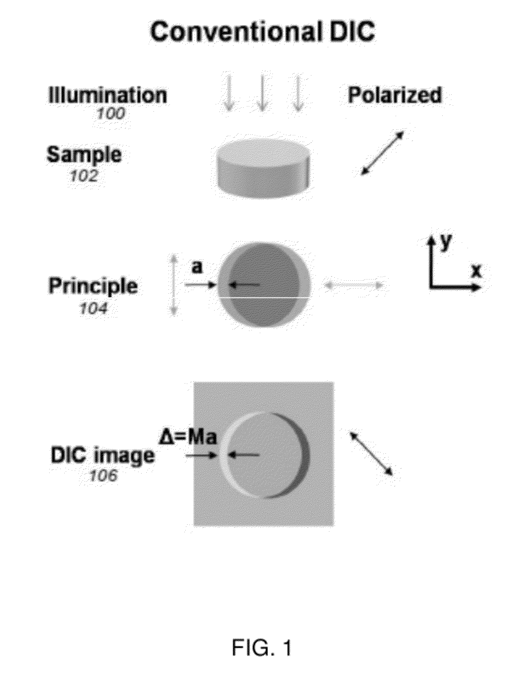
One major disadvantage is that the conventional DIC microscope translates phase variations into amplitude (intensity) variations, and therefore phase variations cannot be easily disentangled from amplitude variations that arise from sample absorption and / or scattering [1].
In addition, conventional DIC images of birefringent samples can have significant artifacts as the conventional DIC microscope depends on polarized light and uses polarization in its phase imaging strategy.

Method used


Image

  • Quantitative differential interference contrast (DIC) microscopy and photography based on wavefront sensors
  • Quantitative differential interference contrast (DIC) microscopy and photography based on wavefront sensors
  • Quantitative differential interference contrast (DIC) microscopy and photography based on wavefront sensors

Examples


Embodiment Construction

[0034]In the following description, reference is made to the accompanying drawings which form a part hereof, and which is shown, by way of illustration, several embodiments of the present invention. It is understood that other embodiments may be utilized and structural changes may be made without departing from the scope of the present invention.

[0035]Overview

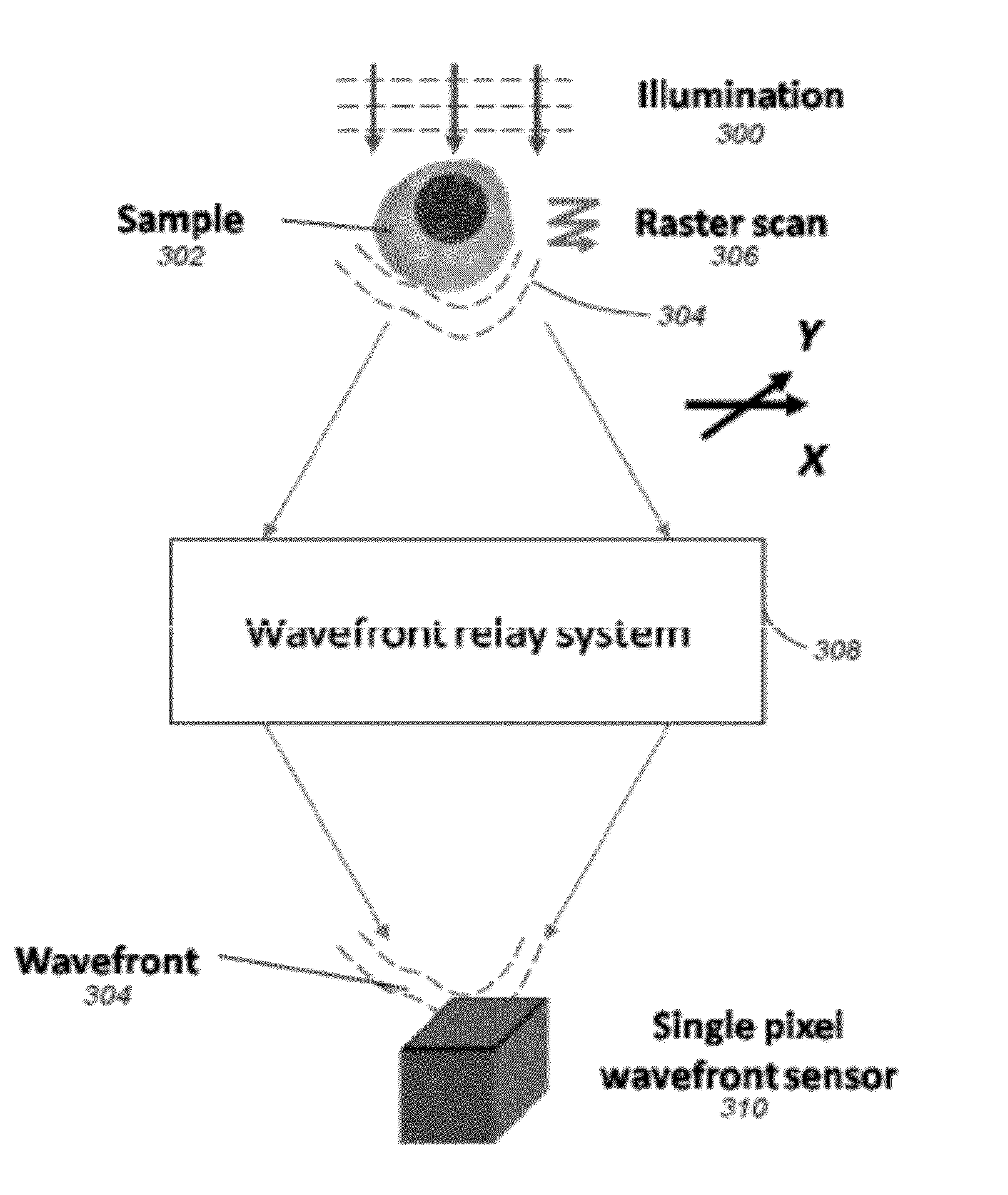
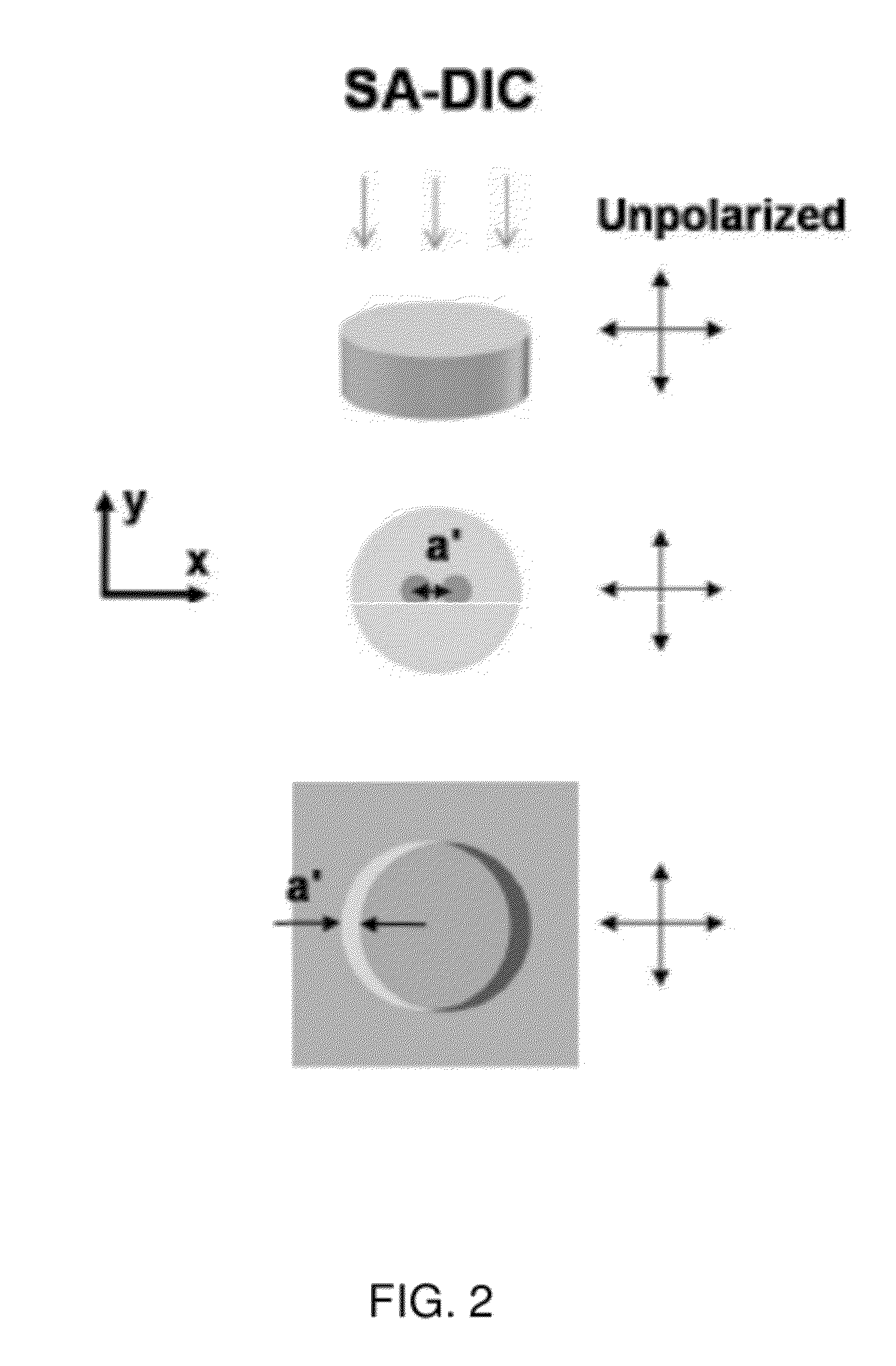
[0036]One or more embodiments of the invention provide a mechanism to create a simple, quantitative and birefringent-artifact-free DIC microscopy or photography method with wavefront sensors.

[0037]Configuration of the Quantitative Differential Interference Contrast (DIC) Microscopy Based on Wavefront Sensors

[0038]Using conventional microscopy, a sample may be illuminated and a photodetector may be used to receive the diffracted light. Two types of information are desirable based on the illumination—(1) the number / distribution of photons; and (2) the direction / wavefront slope / phase gradient of the photons. Conventional microscop...


PUM


Abstract

Embodiments of the present invention relate to a wavefront sensor comprising a film and a photodetector. The film has one or more structured two dimensional apertures configured to convert a phase gradient of a wavefront into a measurable form. The photodetector is configured to receive the wavefront through the one or more 2D apertures and measure the phase gradient of the wavefront.

Description

CROSS-REFERENCES TO RELATED APPLICATIONS[0001]This is a continuation application of co-pending U.S. patent application Ser. No. 12 / 435,165, filed on May 4, 2009, which is a non-provisional of, and claims priority to, U.S. Provisional Patent Application No. 61 / 126,441, filed on May 5, 2008, entitled “QUANTITATIVE DIFFERENTIAL INTERFERENCE CONTRAST (DIC) MICROSCOPY BASED ON WAVEFRONT SENSORS.” These applications are hereby incorporated by reference in their entirety for all purposes.[0002]This application is related to the following commonly-assigned patent applications, which are hereby incorporated by reference in their entirety for all purposes:[0003]U.S. patent application Ser. No. 11 / 743,581, filed on May 2, 2007, by Xiquan Cui, Xin Heng, Demetri Psaltis, Axel Scherer, and Changhuei Yang, entitled “ON-CHIP PHASE MICROSCOPE / BEAM PROFILER BASED ON DIFFERENTIAL INTERFERENCE CONTRAST AND / OR SURFACE PLASMON ASSISTED INTERFERENCE,” now U.S. Pat. No. 7,768,654, which application claims ...

Claims


Application Information

Patent Timeline
Patent Type & Authority Applications(United States)
IPC IPC(8): H01L27/146G01J1/42H01L31/0232
CPCG01J9/02H01L27/14643G02B21/14G02B21/0092
Inventor CUI, XIQUANYANG, CHANGHUEITEARNEY, GUILLERMO J.
Owner CALIFORNIA INST OF TECH
Learn More