Packaged coupler

a coupler and package technology, applied in the field of electronic industry, can solve problems such as poor directivity

Inactive Publication Date: 2012-03-15
STMICROELECTRONICS (TOURS) SAS
View PDF1 Cites 23 Cited by
  • Summary
  • Abstract
  • Description
  • Claims
  • Application Information

AI Technical Summary

Benefits of technology

[0009]An embodiment provides a coupler overcoming all or part of the disadvantages of usual couplers.

Problems solved by technology

The larger the bumps, the poorer the directivity.

Method used


Image

  • Packaged coupler
  • Packaged coupler
  • Packaged coupler

Examples


Embodiment Construction

[0027]The same elements have been designated with the same reference numerals in the different drawings, which have been drawn out of scale. For clarity, only those elements which are useful to the understanding of the present invention have been shown and will be described. In particular, the different upstream and downstream circuits capable of being connected to the coupler have not been detailed, the present embodiments being compatible with present uses of a coupler in radio transceiver chains. Further, the actual coupler manufacturing steps have not been detailed either, the present embodiments being here again compatible with conventional steps.

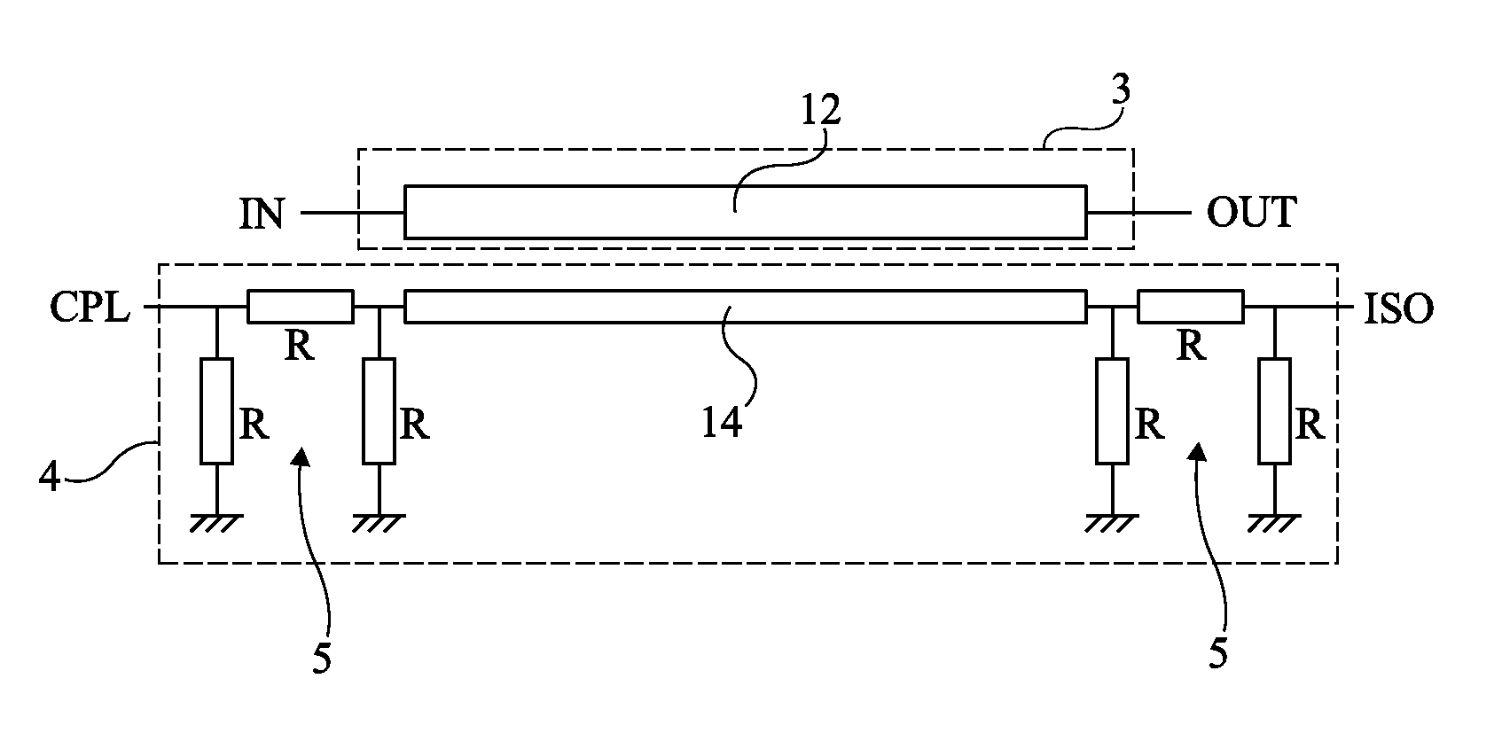
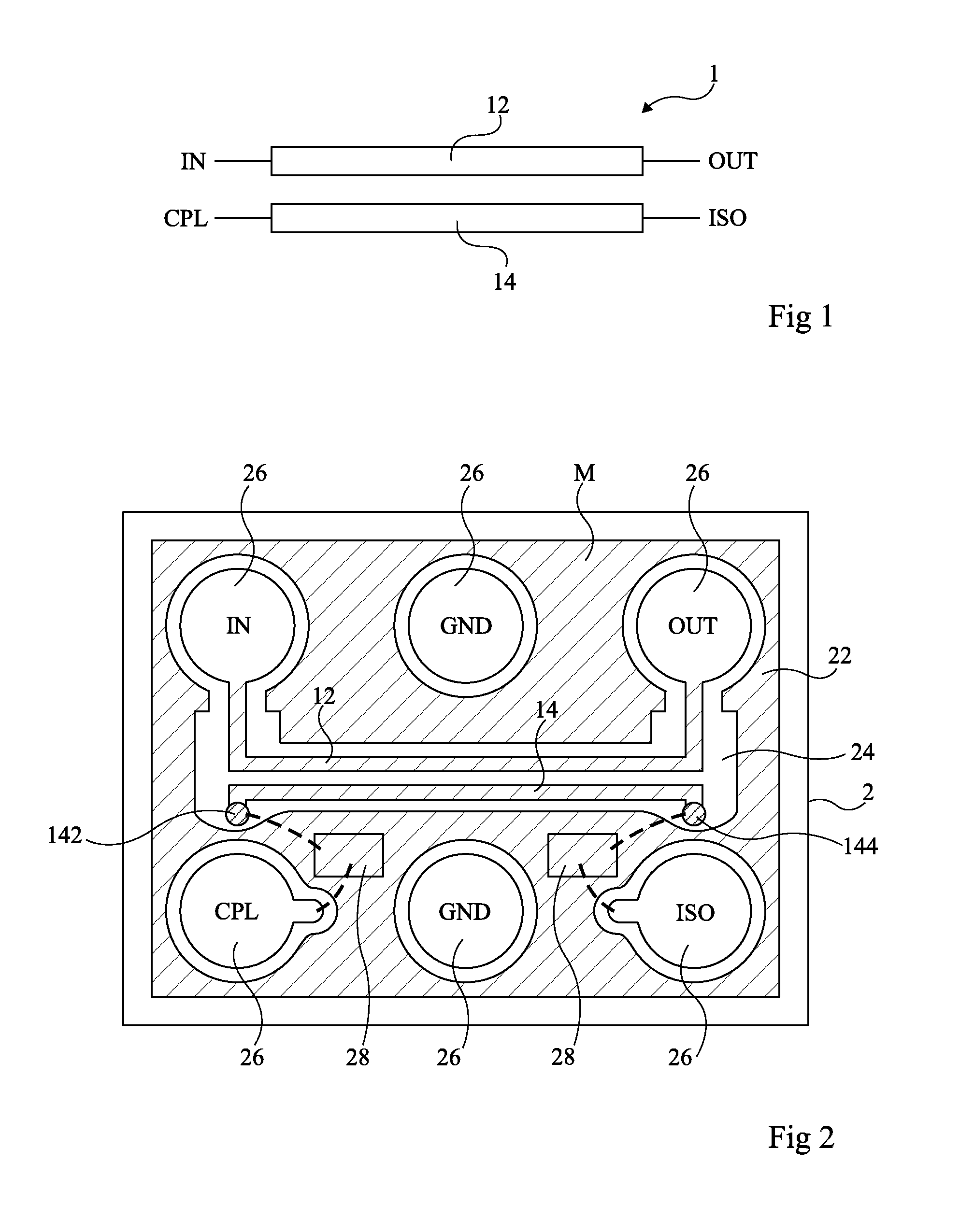
[0028]FIG. 1 schematically shows a distributed coupler 1. The coupler comprises a main line 12 intended to convey a radio signal (received or transmitted). A so-called input port or access IN is located on the signal reception side (on the amplifier side or on the antenna side according to the transmission direction) while a so-called ...


PUM


Abstract

A distributed coupler including a first line intended to convey a radio signal between its two ends and a second line intended to sample, by coupling, part of the signal, wherein: one of the lines is formed on an insulating substrate; and the other line is formed in a lead frame supporting the substrate, one line being above the other.

Description

CROSS REFERENCE TO RELATED APPLICATIONS[0001]This application claims the priority benefit of French patent application number 10 / 57191, filed on Sep. 10, 2010, entitled PACKAGED COUPLER, which is hereby incorporated by reference to the maximum extent allowable by law.BACKGROUND OF THE INVENTION[0002]1. Field of the Invention[0003]The present invention generally relates to the electronics industry and, more specifically, to radio transceiver systems. The present invention more specifically relates to the forming of a coupler in a package.[0004]2. Discussion of the Related Art[0005]A coupler is generally used to recover part of the power present on a so-called main or primary transmission line to provide it to another so-called coupled or secondary line, located nearby. Couplers are divided in two categories according to whether they are formed of discrete passive components (lumped element couplers) or of conductive lines close to one another to be coupled (distributed couplers). The...

Claims


Application Information

Patent Timeline
Patent Type & Authority Applications(United States)
IPC IPC(8): H01P5/18
CPCH01P5/185H01L2924/181H01L2224/16245H01L2224/48091H01L2224/48247H01L2224/73265H01L2924/00012H01L2924/00014
Inventor EZZEDDINE, HILALLAPORTE, CLAIRE
Owner STMICROELECTRONICS (TOURS) SAS
Why Eureka
Try Eureka