
Touch sensitive device with stylus support

a technology of stylus and touch, applied in the field of touch sensitive devices, can solve problems such as speed limitations

Active Publication Date: 2012-03-15
3M INNOVATIVE PROPERTIES CO
View PDF5 Cites 101 Cited by
  • Summary
  • Abstract
  • Description
  • Claims
  • Application Information

AI Technical Summary

Benefits of technology

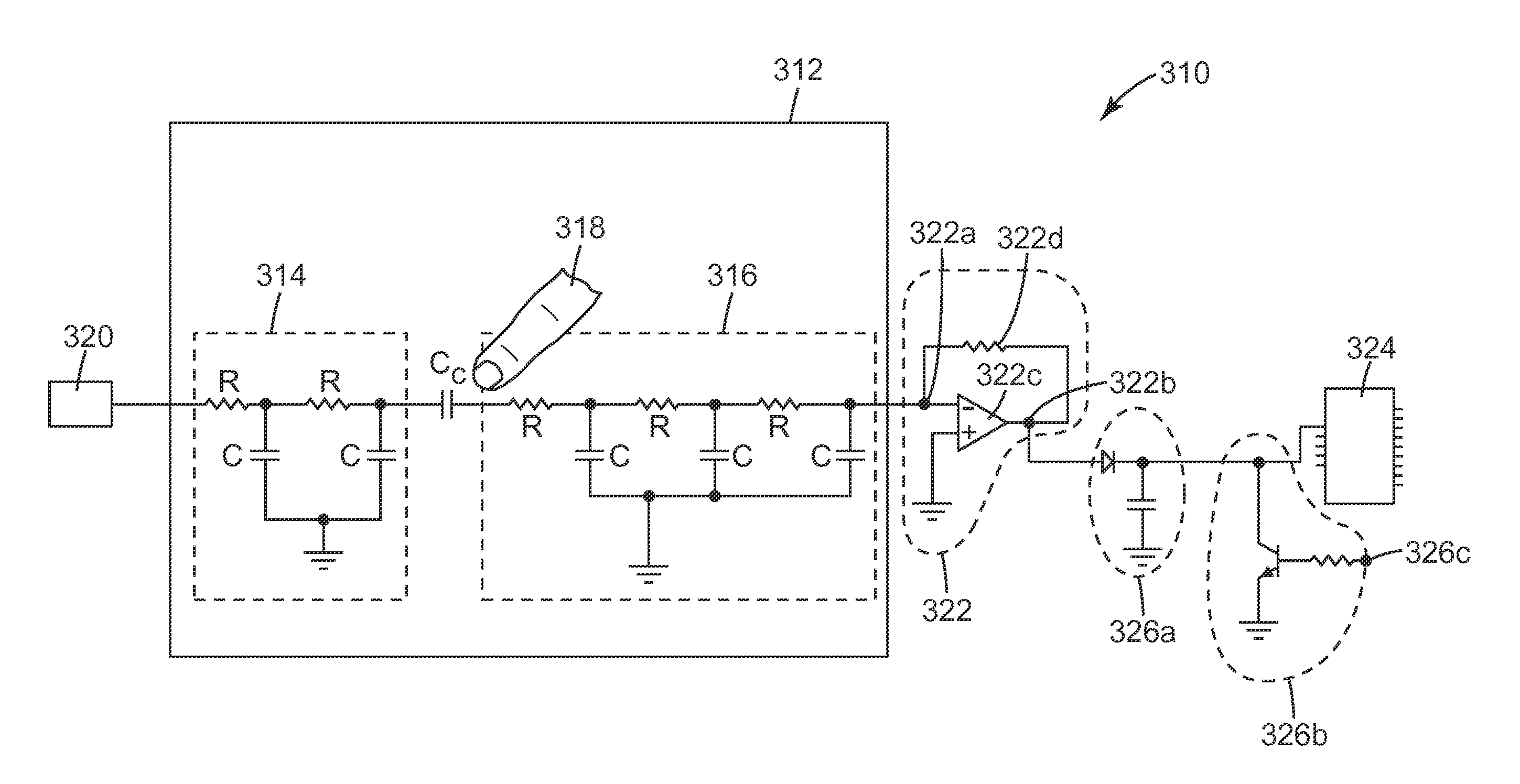
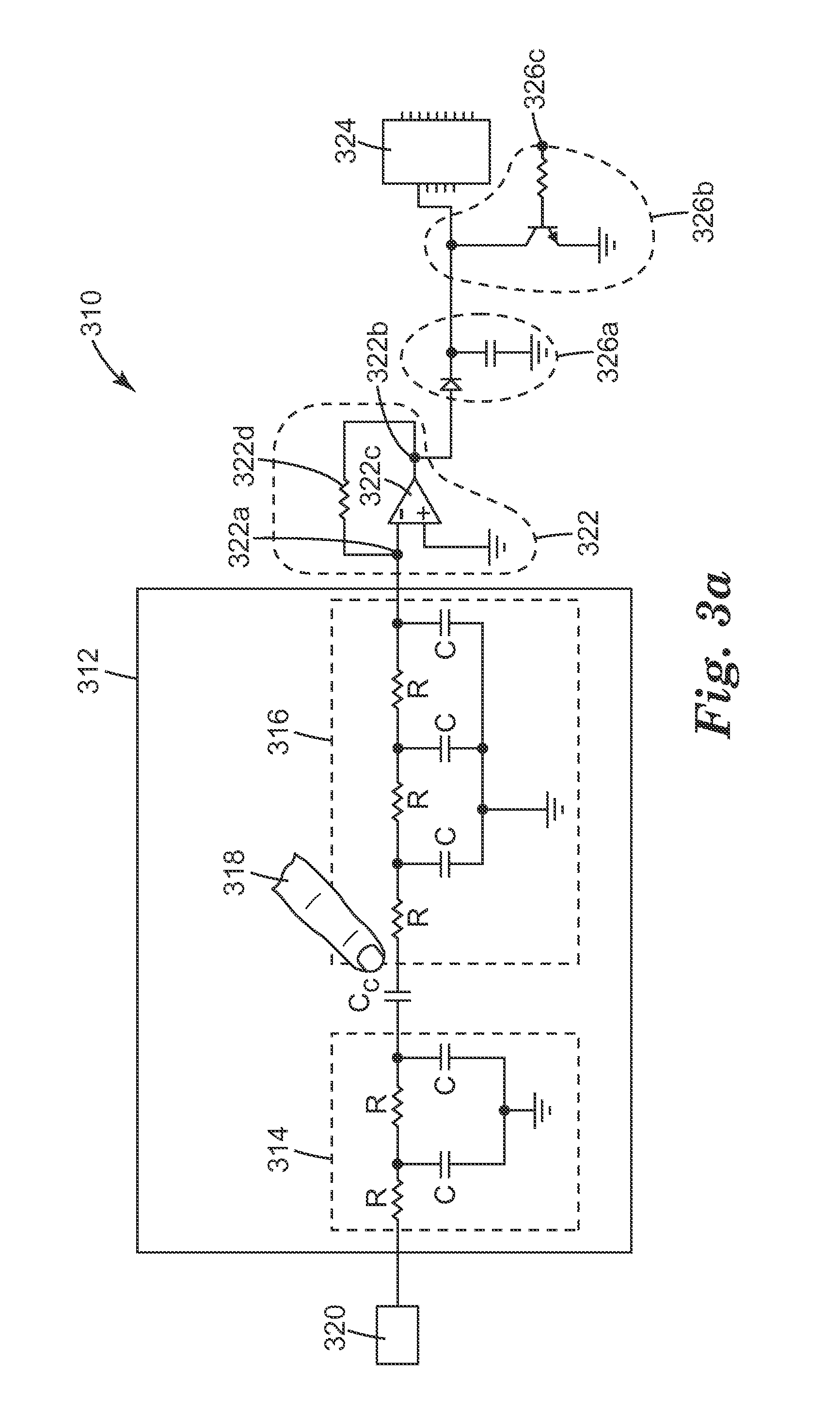
[0009]The present application discloses, inter alia, touch-sensitive devices capable of detecting the presence of one or more objects, including fingers and styli, located proximate to, or touching, different portions of the touch device, at the same time or at overlapping times. In some embodiments, the touch-sensitive devices need not employ an integrating capacitor in order to measure the capacitive coupling between the drive electrodes and the receive electrodes (associated with the touch panel or the stylus). Rather, in at least some embodiments, a single pulse from a drive signal may be all that is necessary to measure the capacitive coupling between a particular drive electrode (which may be arranged in the stylus or in a the touch sensitive device) and a particular receive electrode (which too may be arranged in the stylus or in the touch sensitive d...

Problems solved by technology

This technique has good noise immunity, but its speed may be limited depending upon the number of pulses needed to charge the integrating capacitor.

Method used


Image

  • Touch sensitive device with stylus support
  • Touch sensitive device with stylus support
  • Touch sensitive device with stylus support

Examples


Embodiment Construction

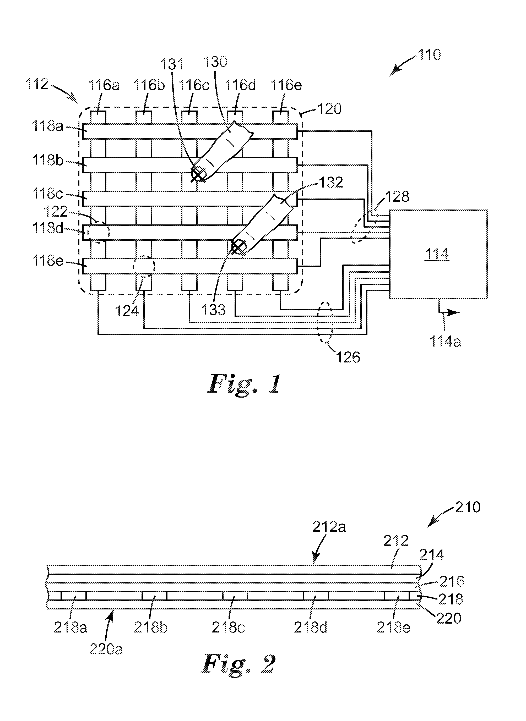
[0034]In FIG. 1, an exemplary touch device 110 is shown. The device 110 includes a touch panel 112 connected to electronic circuitry, which for simplicity is grouped together into a single schematic box labeled 114 and referred to collectively as a controller.

[0035]The touch panel 112 is shown as having a 5×5 matrix of column electrodes 116a-e and row electrodes 118a-e, but other numbers of electrodes and other matrix sizes can also be used. The panel 112 is typically substantially transparent so that the user is able to view an object, such as the pixilated display of a computer, hand-held device, mobile phone, or other peripheral device, through the panel 112. The boundary 120 represents the viewing area of the panel 112 and also preferably the viewing area of such a display, if used. The electrodes 116a-e, 118a-e are spatially distributed, from a plan view perspective, over the viewing area 120. For ease of illustration the electrodes are shown to be wide and obtrusive, but in pr...


PUM


Abstract

A touch-sensitive device with stylus includes a touch panel, a stylus drive unit, a touch panel sense unit, and a measurement unit. A touch by a stylus proximate to a touch panel electrode changes a capacitive coupling between the touch panel electrode and a stylus electrode. The amplitude of the response signal is responsive to the capacitive coupling between the touch panel electrode and the stylus electrode, and is measured to provide an indication of the position of the stylus electrode relative to the touch panel.

Description

CROSS REFERENCE TO RELATED APPLICATIONS[0001]This application is related to U.S. Patent Application Ser. No. 61 / 182,366, “High Speed Multi-Touch Device and Controller Therefor”, filed May 29, 2009; and U.S. Patent Application Ser. No. 61 / 231,471, “High Speed Multi-Touch Device and Controller Therefor” filed Aug. 5, 2009, and U.S. patent application Ser. No. 12 / 652,343, “High Speed Noise Tolerant Multi-Touch Device and Controller Therefor” filed Jan. 5, 2010.FIELD OF THE INVENTION[0002]This invention relates generally to touch-sensitive devices, particularly those that rely on a capacitive coupling between a user's finger or other touch implement and the touch device, with particular application to such devices that are capable of detecting multiple touches (from fingers and styli) applied to different portions of the touch device possible at the same time.BACKGROUND[0003]Touch sensitive devices allow a user to conveniently interface with electronic systems and displays by reducing o...

Claims


Application Information

Patent Timeline
IPC IPC(8): G06F3/044
CPCG06F3/03545G06F2203/04106G06F3/044G06F3/0416G06F3/04166G06F3/0442G06F3/0445G06F3/0446
Inventor WEAVER, BILLY L.HABLE, BROCK A.REBESCHI, THOMAS J.
Owner 3M INNOVATIVE PROPERTIES CO
Learn More