Three-dimensional information presentation device using slit viewing

Active Publication Date: 2012-03-15
JAPAN SCI & TECH CORP
View PDF2 Cites 14 Cited by
  • Summary
  • Abstract
  • Description
  • Claims
  • Application Information

AI Technical Summary

Benefits of technology

[0040]According to the present invention, the presentation unit of the three-dimensional information is the line-light-source unit, which is composed of the simple structure of the combination of the point-light-source column and the slit; and, there is an effect that images having binocular parallax can be easily presented by presenting different images viewed by the left and right

Problems solved by technology

It is cumbersome for a viewer to use glasses or the like, and there is a defect that, for example, the faces of each other cannot be seen.
Therefore, preferably, it is desired to view three-dimensional images by naked eyes; however, the methods not usi

Method used


Image

  • Three-dimensional information presentation device using slit viewing
  • Three-dimensional information presentation device using slit viewing
  • Three-dimensional information presentation device using slit viewing

Examples


Example

First Embodiment

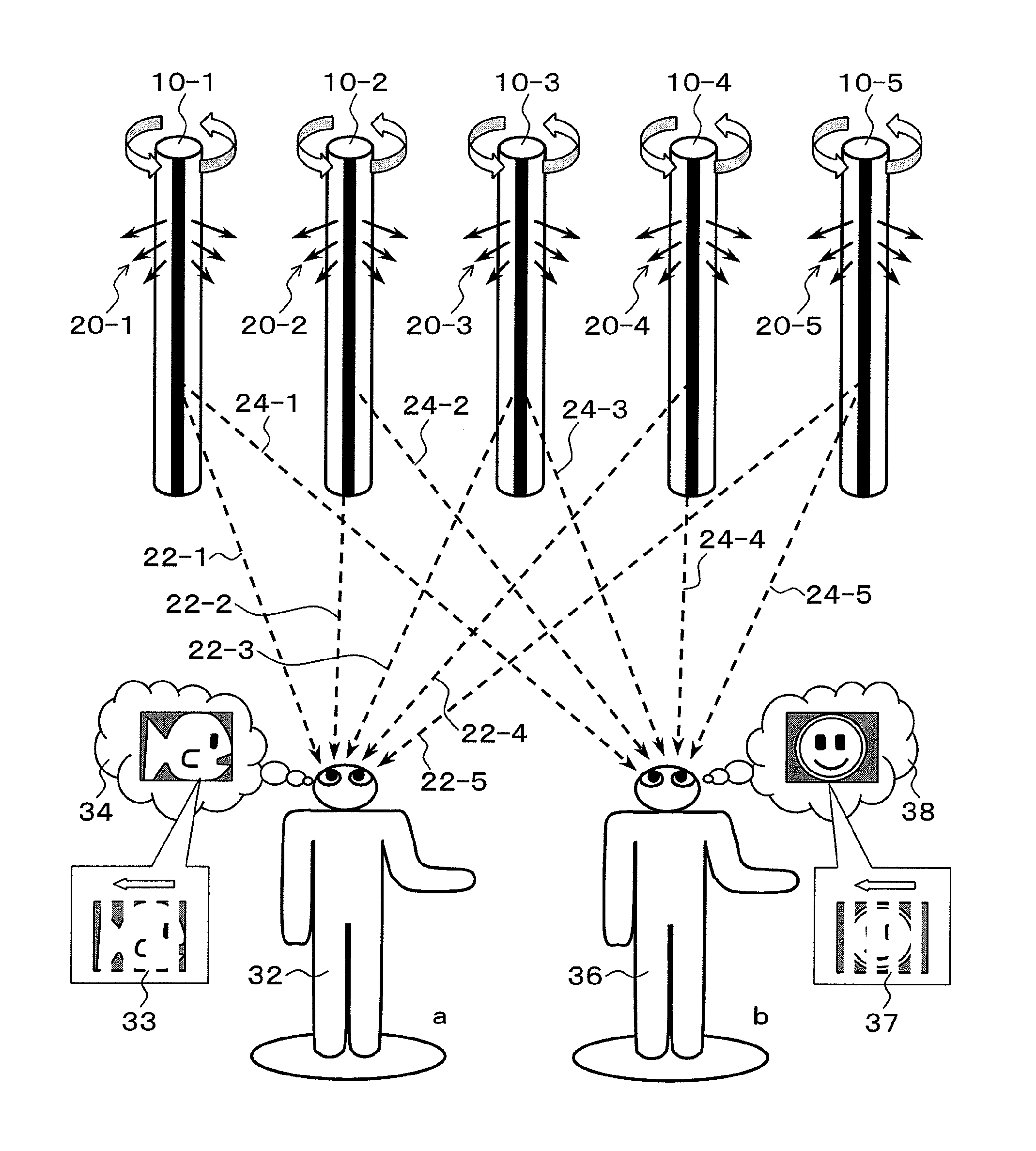
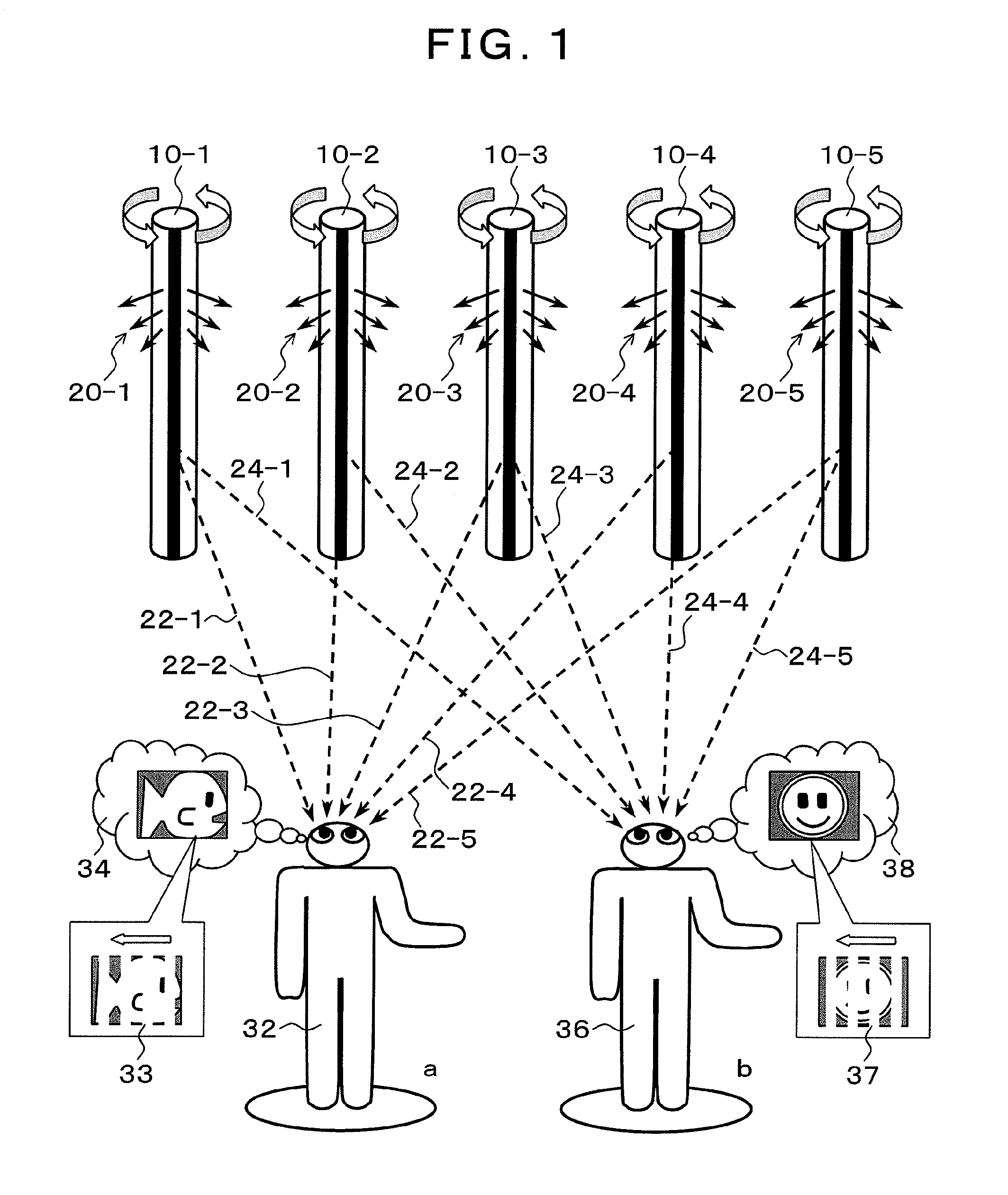
[0064]FIG. 1 is a schematic drawing of the present invention. In FIG. 1, line-light-source units 10-1 to 10-5 radiate light rays 20-1 to 20-5 of images by line light sources of which directions are changed while rotating. Since a viewer a32 and a viewer b36 are at different positions, each of the line-light-source units 10-1 to 10-5 is viewed from different angles. For example, when the viewer a32 views the line-light-source unit 10-3, the light ray is perceived when the unit is in the direction of a light ray 22-3. Meanwhile, the viewer b36 perceives the light ray from the line-light-source unit 10-3 when the unit is in the direction of a light ray 24-3. Therefore, when different images are presented from the line-light-source units 10-1 to 10-5, respectively, when the angles thereof are in the directions that enable the viewer a32 and the viewer b36 to view the images, the viewer a32 perceives an image 34, and the viewer b36 perceives an image 38. In the present in...

Example

Second Embodiment

[0080]In the first embodiment, the configuration in which both of the line-light-source element and the slit are integrally rotated has been shown in detail. However, the number of the rotating slit is one, and the light source can stand still if light is emitted in the directions of 360 degrees.

[0081]FIG. 16 is a study drawing for emitting light in the directions of 360 degrees. It is conceived that the isoperimetric surface on which the slit rotates is to be divided into equal angles by an angle α. If α is 180 degrees, two point-light-source columns are required; if α is 120 degrees, three line-light-source elements are required; and, if α is 90 degrees, four line-light-source elements are required. However, although two line-light-source elements are enough for the case in which α is 180 degrees, in reality, the parts of the line-light-source elements have thicknesses, and, on the parallel surfaces of the parts sandwiching the central axis, there are ranges in wh...

Example

Third Embodiment

[0084]As an example in which the second embodiment is applied, an embodiment about a method of providing slits so as to correspond to point-light-source columns of line-light-source elements in a mult-ray light-source unit will be explained.

[0085]FIG. 19 shows the structure of a line-light-source unit of the case in which three line-light-source elements of a light-source unit 202 are provided, and a light shield 204 is provided with slits 202-1 to 202-3 corresponding to respective point-light-source columns. The light-source unit 200 provided with the slits corresponding to the plurality of point-light-source columns is referred to as a multi-slit line-light-source unit. A basic method of usage of the multi-slit line-light-source unit 200 is rotation of only the slits; however, if the point-light-source columns and the slits are rotated at the same time, light rays multiplied by three are emitted; therefore, the speed of rotation becomes one third compared with the ...


PUM


Abstract

Provided is a device which can present three dimensional information by a simple structure and in which the information can be viewed with the naked eye. A plurality of rotary line-light-source units are arranged. The line-light-source units provide different pieces of image information in different directions, in order to produce a parallax between both eyes. A three-dimensional image control unit performs a control to provide thinned image information at corresponding positions to the plurality of line-light-source units and successively present the entire three-dimensional image information by scrolling. As a result, a viewer can recognize the three-dimensional image moved and presented by the scroll control.

Description

TECHNICAL FIELD[0001]The present invention relates to a three-dimensional information presentation device that enables naked eyes to view stereoscopic images by rotating a slit and changing the direction of light rays.BACKGROUND ART[0002]In order to display a three-dimensional stereoscopic image, physiological stereoscopic elements by which a person senses the stereoscopic feeling and perspective are utilized. The physiological stereoscopic elements include: binocular parallax which is the difference between the images viewed by the left and right eyes, binocular convergence which is the rotation angle of eye balls serving as an intersecting point of visual lines, focal-point adjustment which is change in the thickness of a lens for adjusting the focal point, and kinematic parallax which is the difference between the images viewed by eyes because of movement. Among these physiological stereoscopic elements, binocular parallax is conventionally utilized in display of three-dimensiona...

Claims


Application Information

Patent Timeline
IPC IPC(8): G02B27/22G02B30/30
CPCG02B27/225G02B27/2285G09F9/33G09G3/004G09F19/14G09F27/00G09G3/003G09F11/02G02B30/54G02B30/30
Inventor WATANABE
Owner JAPAN SCI & TECH CORP
Why Eureka
Try Eureka