Autostereoscopic display device

a display device and autostereoscopic technology, applied in the direction of illuminated signs, display means, instruments, etc., can solve the problems of reducing the resolution of the display device, reducing the number of views generated, and simple barrier arrangement, etc., to reduce the number and eliminate the boundaries of the viewing cone

Inactive Publication Date: 2012-03-15
KONINKLIJKE PHILIPS ELECTRONICS NV
View PDF5 Cites 85 Cited by
  • Summary
  • Abstract
  • Description
  • Claims
  • Application Information

AI Technical Summary

Benefits of technology

[0011]One object of the invention is to reduce the number of, and preferably to eliminate the viewing cone boundaries.

Problems solved by technology

A drawback of this type of two-view display design is that the viewer has to be at a fixed position, and can only move approximately 3 cm to the left or right.
The barrier arrangement is simple to produce but is not light efficient.
This sacrifice in resolution increases with the number of views generated.
Thus, a major drawback of using a high number of views is that the image resolution per view is reduced.
Increasing the number of views thus improves the 3D impression but reduces the image resolution as perceived by the viewer.
The viewing experience is hampered by the fact that the viewers are not entirely free in choosing their location within the field of view of the display device, i.e. their location from which to view a 3D monitor or television in the sense that at the boundaries between viewing cones within the field of view of the display, the 3D effect is absent and annoying ghost images appear.

Method used


Image

  • Autostereoscopic display device
  • Autostereoscopic display device
  • Autostereoscopic display device

Examples


first embodiment

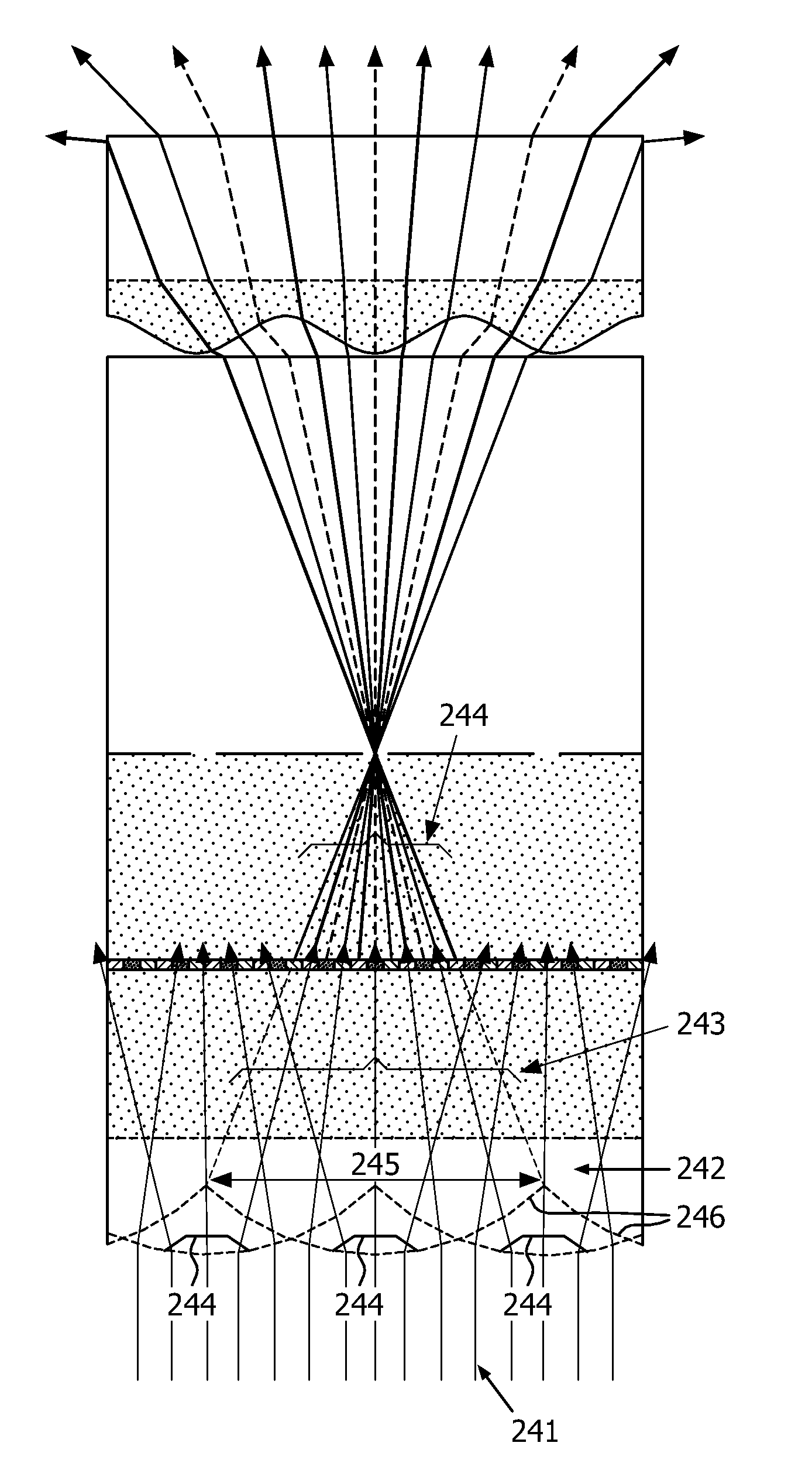
[0078]A first embodiment according to the invention will be described next with reference to FIG. 7, which shows the ideal solution of the problem of the occurrence of repeated cones and cone transitions. FIG. 7 shows a system 70 having only a single cone 71 consisting of many views (i.e. the angle (Φ) is close to)180°, so that there are no cone transitions. Thus, the viewing cone width is the same as the field of view of the system 70.

[0079]FIG. 8 shows a basic embodiment for such a “single cone” display. It consists of a display having a display panel with a pixel plane 86 equipped with a barrier 80 with relatively narrow transparent apertures (slits) 82. The barrier is spaced from the display panel with a distance D. The light 84 stemming from a backlight lighting arrangement (not shown) enters the glass 81 of the display from the backlight-side. Inside the glass, the angle of the incoming light with the display normal varies between 0° and 42° (assuming that the light from the b...

second embodiment

[0094]An autostereoscopic device 100 according to the invention is described with reference to FIG. 10. Again, there is only a single viewing cone spanning the field of view 102. In this case, the density of views is high at small viewing angles and low at large viewing angles. This results in a good 3D image quality at relatively small viewing angles (in the lateral direction) for e.g. viewer 105 and a good 2D image quality at larger viewing angles for e.g. viewer 104.

[0095]Thus, the views 101 including e.g. views 101′, 101″ and 101′″ are distributed in a non-linear manner. That is to say, the views are arranged such that the view spacing is small for views leaving the display almost perpendicularly (i.e. small viewing angles such as e.g. view 101′″). For increasing viewing angle, the view spacing is increased (such as for e.g. views 101″ and 101′). Not all views thus have the same view width.

[0096]As mentioned above, the smaller the angular spacing between neighboring views the m...

third embodiment

[0120]A third embodiment with increased barrier lens distance is shown in FIG. 14a. The main lens is cosine-shaped. When compared to the previous embodiment, the barrier-lens distance has doubled. The lens pitch has remained the same, but the lens touches the underlying glass only once per pitch. The rays coming through a barrier aperture are “captured” by actually two (or, alternatively, half+one+half) lenses. A part of the lens that acts as “central part” for one barrier aperture acts as “edge part” for the neighboring aperture. Each part of the lens is used two times, i.e. irradiated from two apertures. The advantage is that the lens can be less curved in the centre. As a result the barrier aperture can be increased and a less negative lens is needed to collimate the central views. In this case, the ratio of the distance dl of the lenses 120 from the display panel 86 to the distance db of the barrier arrangement 80 from the display panel 86 is preferably in the range 2.5 to 3.5.

[...


PUM


Abstract

An autostereoscopic display device has both a barrier arrangement and a lens arrangement. A plurality of views are provided to different lateral viewing directions. At least a portion of the field of view has autostereoscopic output, and the portion having autostereoscopic output has no repetition of individual 2D views and comprises at least three individual 2D views. This means there is no reversal of the stereo views (“pseudo stereo views”) at viewing cone boundaries as there are no viewing cone boundaries.

Description

FIELD OF THE INVENTION[0001]This invention relates to an autostereoscopic display device of the type that comprises a display panel having an array of display pixels for producing a display and an imaging arrangement for directing different views to different spatial positions.BACKGROUND OF THE INVENTION[0002]A first example of an imaging arrangement for use in this type of display is a barrier, for example with slits that are sized and positioned in relation to the underlying pixels of the display. In a two-view design, the viewer is able to perceive a 3D image if his / her head is at a fixed position. The barrier is positioned in front of the display panel and is designed so that light from the odd and even pixel columns is directed towards the left and right eye of the viewer, respectively.[0003]A drawback of this type of two-view display design is that the viewer has to be at a fixed position, and can only move approximately 3 cm to the left or right. In a more preferred embodimen...

Claims


Application Information

Patent Timeline
Patent Type & Authority Applications(United States)
IPC IPC(8): G02B27/22G09F13/04
CPCH04N13/0404H04N13/0456H04N13/0447H04N13/0411H04N13/305H04N13/312H04N13/351H04N13/361G02B30/00
Inventor KRIJN, MARCELLINUS PETRUS CAROLUS MICHDE ZWART, SIEBE T.PULMAN, FETZEDESMET, LIEVEN R.R.WILLEMSEN, OSCAR HENRICUS
Owner KONINKLIJKE PHILIPS ELECTRONICS NV
Why Eureka
Try Eureka