
A method and a device for coating ceramic material fibers in metal by a liquid technique

a ceramic material fiber and liquid technology, applied in the direction of coatings, liquid surface applicators, metallic material coating processes, etc., can solve the problems of low productivity of that type of coating method, inability to optimize, and the quality of the coated fiber obtained by a liquid coating method, so as to achieve moderate cost and great length

Active Publication Date: 2012-03-15
SN DETUDE & DE CONSTR DE MOTEURS DAVIATION S N E C M A
View PDF1 Cites 9 Cited by
  • Summary
  • Abstract
  • Description
  • Claims
  • Application Information

AI Technical Summary

Benefits of technology

[0009]A main object of the present invention is thus to mitigate such drawbacks by proposing a coating method and a coating device that enable coated fibers to be made that are of great length and of moderate cost.
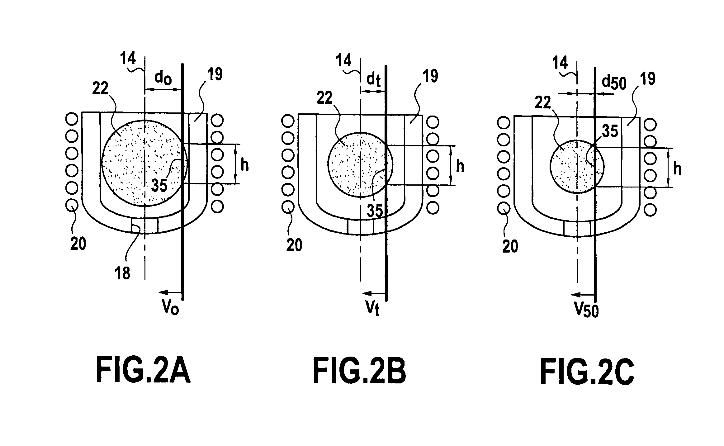
[0012]The invention thus proposes shifting the fiber thorough the charge of metal as a function of the reduction in its weight in such a manner as to keep constant the instantaneous height of fiber that is immersed. This solution presents numerous advantages.
[0013]In particular, the length of coated fiber that is obtained by the method can be increased by a factor of at least 5 while using a single charge, i.e. without any need to incorporate new material. Furthermore, in the absence of any new material, the molten charge presents good uniformity and the quality of the coating is thereby improved. As a result, the method of the invention makes it possible to obtain coated fibers of good quality and of so-called “medium” lengths (i.e. lying in the range 200 meters (m) to 600 m for charges presenting a volume of 50 cm3 and coatings presenting thicknesses of 50 μm), at a cost that is moderate. Greater lengths are possible by adapting the size of the crucible to the volume of the initial charge. Thus, lengths exceeding a kilometer can be obtained using charges of about 150 cm3.
[0014]Furthermore, this method of the invention can be implemented while keeping all of the other parameters constant during coating. In particular, and advantageously, the travel speed of the fiber between the pulleys can be maintained substantially constant throughout coating, thereby avoiding problems with cooling of the coated fiber. Finally, in order to obtain coated fibers of very great length, this solution does not impede having recourse in parallel to the above-described technique that consists in refilling the metal batch.

Problems solved by technology

As a result, the thickness of the coating varies continuously along the coated fiber until the nominal conditions for coating are no longer satisfied, which means that coating must be interrupted.
Consequently, the quality of the coated fiber that is obtained by a liquid coating method, even though it remains acceptable, is not optimized insofar as the thickness of the coating is not constant over the entire length of the coated fiber.
Correspondingly, the productivity of that type of coating method is relatively low since the length of coated fiber is limited.
Nevertheless, that solution presents the drawback of being relatively expensive since means for delivering fibers or powders are themselves expensive.
Furthermore, incorporating new matter into a given bath can lead to instabilities that are harmful to the coating process.

Method used


Image

  • A method and a device for coating ceramic material fibers in metal by a liquid technique
  • A method and a device for coating ceramic material fibers in metal by a liquid technique
  • A method and a device for coating ceramic material fibers in metal by a liquid technique

Examples


Embodiment Construction

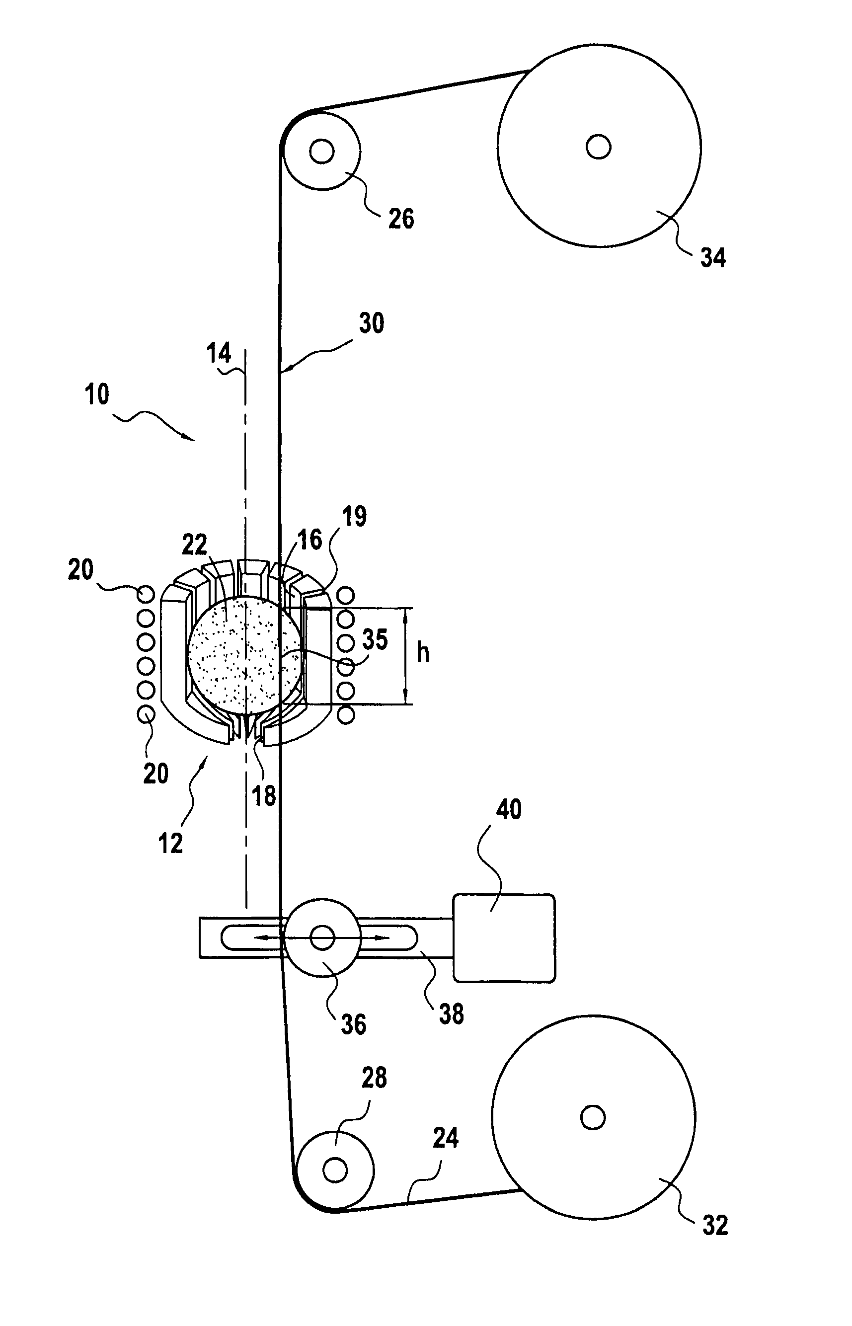
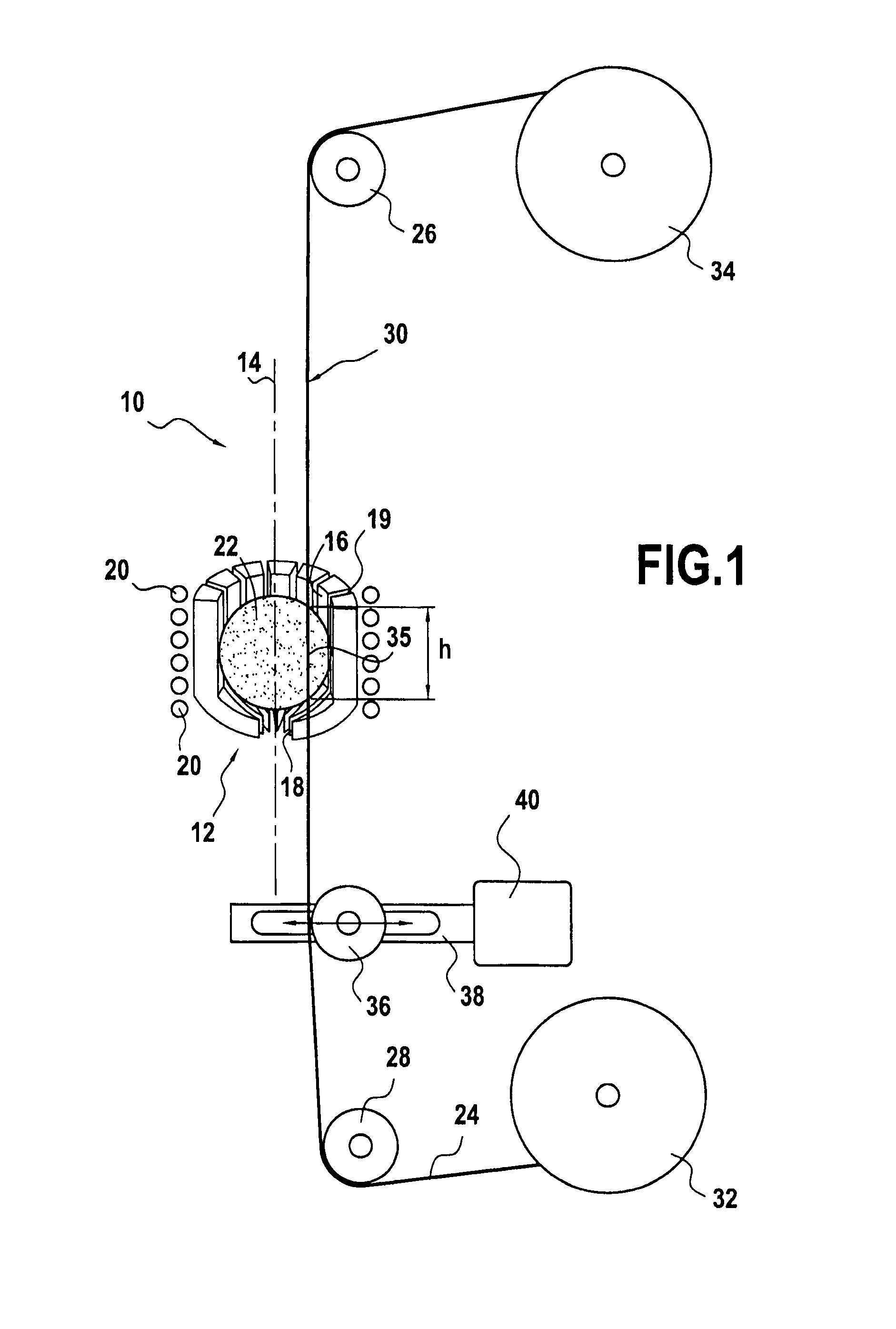
[0020]FIG. 1 shows a device 10 of the invention for coating ceramic material fibers with metal by a liquid technique.

[0021]The device 10 comprises in particular a crucible 12 of the cold type, also referred to as a “levitation” crucible, that is designed to avoid contaminating the molten metal with the material that constitutes its own wall. This type of crucible is itself well known and is therefore not described in greater detail herein. If necessary, reference may be made to document EP 0 931 846 which describes an embodiment.

[0022]The crucible 12 is in the form of a bowl that is circularly symmetrical about a vertical axis 14. It has a top opening 16 that is larger than a bottom opening 18, these openings being circular and centered on the vertical axis 14. As shown in FIG. 1, it also includes a plurality of vertical slots 19 that extend between its openings 16 and 18. In known manner, these vertical slots 19 enable its electrical impedance to be matched and encourage cooling of...


PUM

PropertyMeasurementUnit
Volumeaaaaaaaaaa
Speedaaaaaaaaaa
Heightaaaaaaaaaa

Abstract

A method of coating ceramic material fibers in metal using a liquid technique and a device implementing the method. The method maintains a charge of molten metal in levitation in a substantially spherical shape inside a crucible and causes a tensioned ceramic material fiber to travel at a predetermined speed between a bottom pulley and a top pulley disposed on either side of the crucible such that a portion of fiber is immersed in the charge to be covered in a metal coating. During coating, the portion of fiber that is immersed in the charge is shifted as a function of the remaining volume of the charge such that the instantaneous height of fiber that is immersed in the charge remains substantially constant throughout the coating operation.

Description

BACKGROUND OF THE INVENTION[0001]The present invention relates to the general field of metal matrix composite materials. More particularly, it relates to a method and to a device for coating ceramic material fibers in metal by a liquid technique.[0002]One of the fields of application of the invention is that of aviation, and more precisely that of turbojets in which having recourse to metal matrix composite materials enables significant weight savings to be achieved.[0003]In known manner, metal matrix composite materials are constituted by a matrix based on a metal alloy that is reinforced by fibers, the fibers being made of ceramic, for example. Such materials present high level performance in terms of stiffness and strength and they can be used instead of monolithic alloys in order to make turbojet parts such as disks for compressors or turbines, shafts, actuator cylinders, etc.[0004]In advantageous manner, metal matrix composite materials can also be used for providing local rein...

Claims


Application Information

Patent Timeline
IPC IPC(8): B05D1/18B05C3/15
CPCB22F2999/00B05D2203/30C04B41/4584C04B41/88C04B2111/00931C04B2111/00982C22C47/04C23C2/003C23C2/24C23C2/38C04B41/009B05D2256/00C04B41/4523C04B41/5133C04B14/46C04B14/4693C22B9/221C23C2/0035C23C2/524
Inventor FRANCHET, JEAN-MICHEL PATRICK MAURICEKLEIN, GILLES CHARLES CASIMIRSANCHEZ, GERALD
Owner SN DETUDE & DE CONSTR DE MOTEURS DAVIATION S N E C M A
Learn More