Demand and supply control apparatus, demand and supply control method, and program

a technology of demand and supply control and control method, applied in non-electric variable control, process and machine control, instruments, etc., can solve the problems of temporal mismatch between the demand of electric power and the demand of heat in a building, not only temporal mismatch, but quantitative mismatch between, so as to reduce the cost of operation of the energy devices to be controlled

Inactive Publication Date: 2012-03-15
PANASONIC CORP
View PDF12 Cites 19 Cited by
  • Summary
  • Abstract
  • Description
  • Claims
  • Application Information

AI Technical Summary

Benefits of technology

[0024]According to an aspect of the present invention, when an energy device is newly added to the system, control parameters according not to the past input-output relationships before the addition but to the current input-output relationships after the addition are calculated. The cost of operation of the energy devices to be controlled can therefore be reduced. Also, a manager having expert knowledge can be saved from having to redo calculation of the model based on theory.

Problems solved by technology

This is because in general, there is a temporal mismatch between the demand of electric power and the demand of heat in a building.
There is not only a temporal mismatch but also a quantitative mismatch between the supply of electricity and heat by a co-generation system, and the demand of electricity and the demand of heat.

Method used


Image

  • Demand and supply control apparatus, demand and supply control method, and program
  • Demand and supply control apparatus, demand and supply control method, and program
  • Demand and supply control apparatus, demand and supply control method, and program

Examples


Embodiment Construction

[0044]An Embodiment of the present invention will be hereinafter described with reference to the drawings.

[0045]It is to be noted that even by the operation described with reference to FIG. 15 in other Embodiments described below, the operation cost of energy devices to be controlled can be reduced and a manager having expert knowledge can be saved from having to redo calculation based on theory. The description with reference to FIG. 15, for example, may be referred to first.

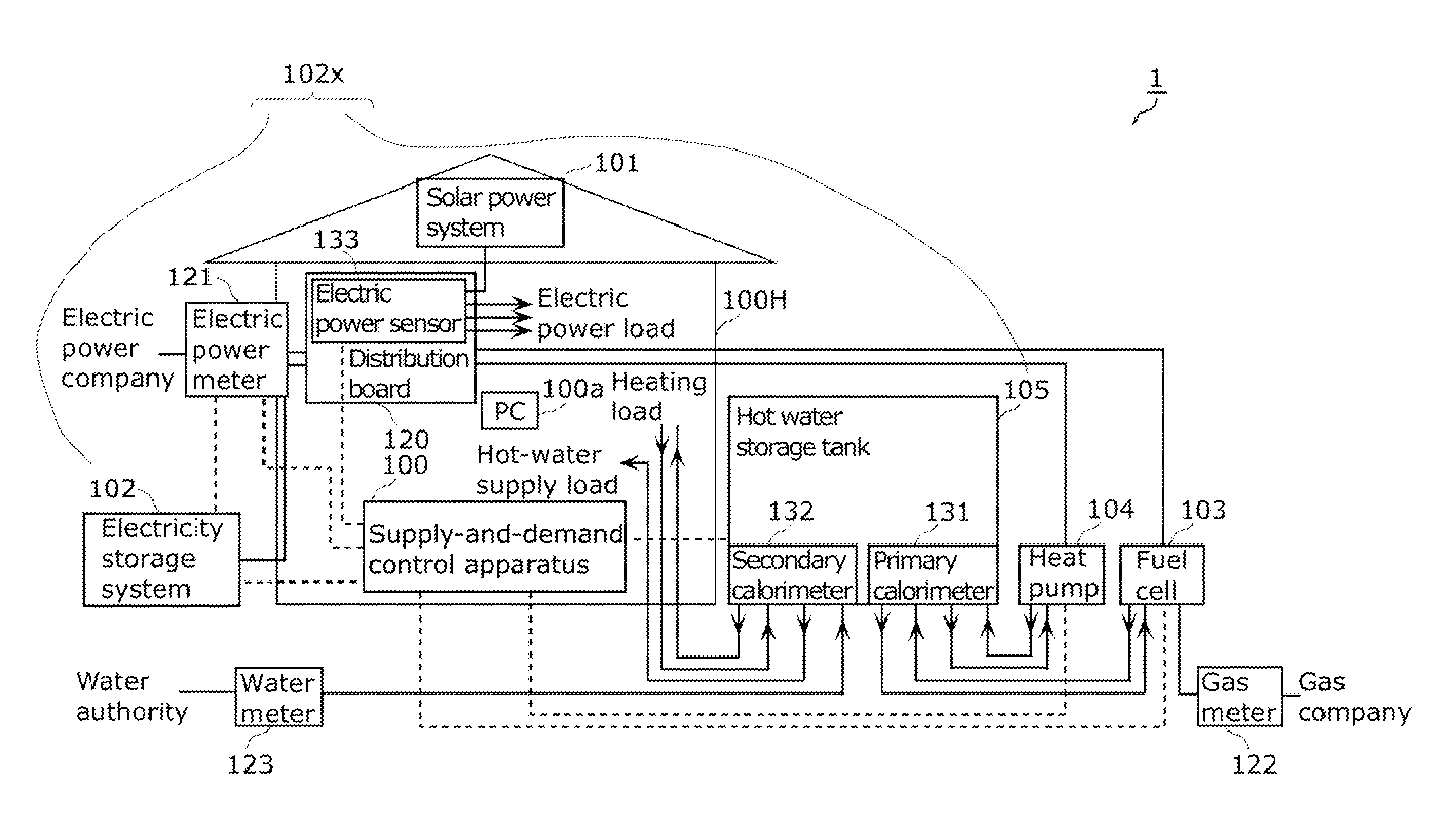
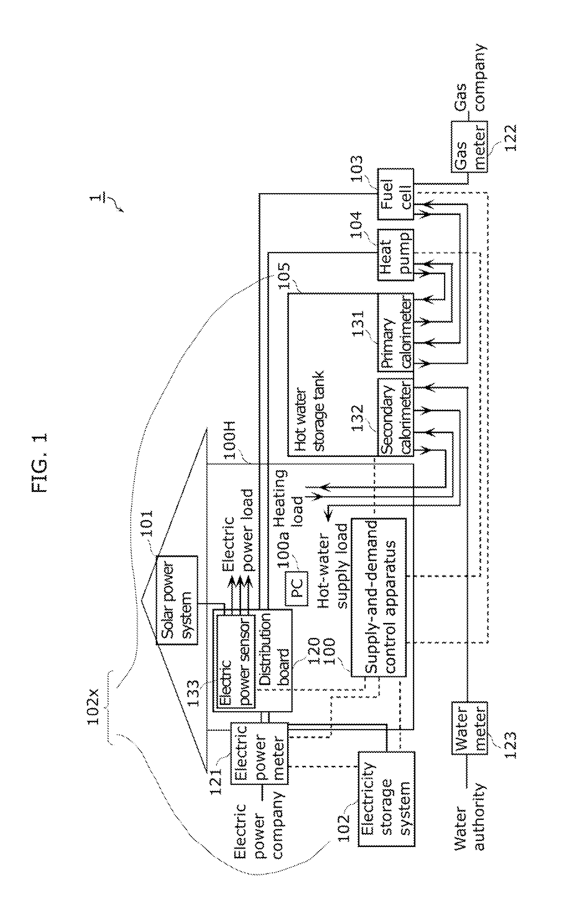
[0046]FIG. 1 illustrates an example of a system configuration of an energy supply system 1 in this Embodiment.

[0047]The energy supply system 1 is installed in a building, such as a house. The building includes demand-side devices (see demand-side device 11c in FIG. 7) including a device that operates on electric power (electric power load), a device such as a hot-water supply device using hot water (hot-water supply load), and a device with which heating is performed by the heat of hot water (heating load). Ene...


PUM


Abstract

A supply-and-demand control apparatus (100) is used that includes an input-output relationship obtaining unit (1001) that obtains information (100i) on energy input-output relationships between a plurality of energy devices including an added energy device, an operation planning unit (1002) that calculates, from the information (100i), the values of control parameters to the plurality of energy devices including the added device, and a supply-and-demand control unit (1003) that sends the calculated values as commands to the plurality of energy devices including the added device.

Description

TECHNICAL FIELD[0001]The present invention relates to control of a system in which energy, such as electricity and heat, is supplied to a building and, more particularly, to a method of calculating a plan for operation of energy devices used for the system such as an electric generator and a heat source device.BACKGROUND ART[0002]Conventionally, systems have been studied in which energy devices that operate using renewable energies are introduced into a building. With such systems, a trial has been made to reduce, by efficiently operating such energy devices, CO2 discharged with energy consumption in a building.[0003]As one of such systems, a co-generation (combined heat and power) system is attracting attention in which an electric generator is installed in a building or the like to simultaneously supply electricity and heat generated during power generation by the electric generator. In wide regions including Europe, residual heat generated simultaneously with power generation is ...

Claims


Application Information

Patent Timeline
Patent Type & Authority Applications(United States)
IPC IPC(8): G06F1/26
CPCH02J3/14H02J13/0017Y04S40/12Y02B90/2607Y04S20/222Y02B70/3225H02J2310/12H02J13/00004H02J13/00034H02J13/00006Y02B90/20
Inventor KAJI, MITSURU
Owner PANASONIC CORP
Why Eureka
Try Eureka