Flow Control Apparatus

a flow control and flow control technology, applied in the direction of cleaning apparatus, fluid removal, borehole/well accessories, etc., can solve the problems of poor performance and productivity of wells, or significantly decline, and achieve the effect of improving the placement of treatment fluids

Active Publication Date: 2012-03-22
WEATHERFORD UK LIMITED
View PDF1 Cites 11 Cited by
  • Summary
  • Abstract
  • Description
  • Claims
  • Application Information

AI Technical Summary

Benefits of technology

[0013]A further advantage of the present invention is that the second ICD can serve as a back-up to the first ICD, should the first ICD become ineffective or inoperable during use.
[0014]The first inflow control device may be provided at one end of the screen and the second inflow control device may be provided at the opposite end of the screen. The orientation of the first and second screens may be such that they both face inwardly towards the screen.
[0015]The apparatus may comprise one or more further inflow control devices. Screens may be provided between each inflow control device.
[0016]The apparatus may further comprise an ICD locator configured for the alignment of a treatment tool to deliver targeted treatment fluid through at least one of the first or second inflow control devices. As such, improved placement of the treatment fluid for use in the flow control apparatus can be achieved. It will be understood that in certain embodiments, a treatment tool can be accurately positioned to straddle the flow control apparatus so that treatment fluid can be forced through an adjacent first ICD before flowing back through the second ICD. In a particular embodiment, the ICD furthest from the surface may be targeted with the treatment tool so that the treatment fluid can flow back through the nearest ICD and up to the surface.
[0017]The ICD locator may be constituted by a recess or an inwardly projecting ledge, shoulder or other projection on which the treatment tool can be located. The ICD locator may be retractable or collapsible (for example, by pressure activation or deactivation) so as to allow the treatment tool to pass by. In certain embodiments, the ICD locator may comprise a welding ring, a spring-loaded (e.g. dog) clip, or an inflatable straddle.
[0018]Each of the first and second inflow control devices may be provided for reservoir management. For example, the first and / or second ICDs may be configured to limit the inflow of oil, gas or water into the production tubing from the surrounding wellbore formations. Accordingly, the first and / or second ICDs may be of the type described in GB2448069 having an inner member and an outer member with a flow path therebetween and an elastomer member disposed within the outer member and adjacent the flow path, the elastomer member being capable of swelling on contact with an actuating agent to thereby restrict the inflow of oil, gas or water.

Problems solved by technology

If, however, the DIF in the wellbore is not replaced by or conditioned to a low or zero solids system, and the ICD screen completions are lowered into an unconditioned section of mud which contains solids, the ICD screen completions may plug and, as a result, well performance and productivity may be poor or significantly decline.

Method used


Image

  • Flow Control Apparatus
  • Flow Control Apparatus
  • Flow Control Apparatus

Examples


Embodiment Construction

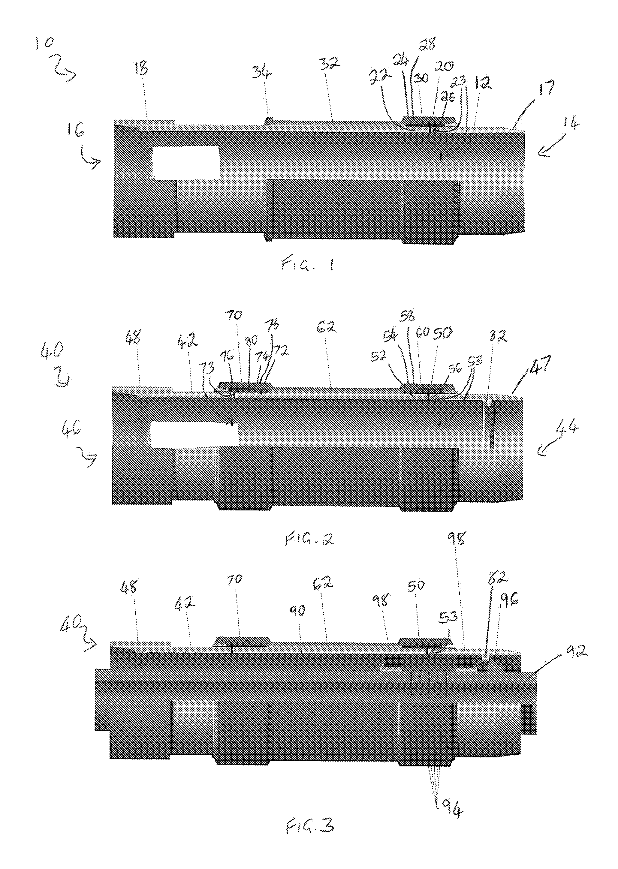
[0041]With reference to FIG. 1, there is illustrated a known flow control apparatus 10 comprising a tubular metal base pipe 12 having a first end 14 and a second end 16. A male coupling 17 is provided at the first end and a female coupling 18 is provided at the second end 16 for attachment to further pieces of completion equipment (not shown). Towards the first end 14 there is provided a single inflow control device (ICD) 20 which comprises an inner member 22 constituted by the base pipe 12 and having a series of apertures 23 therein, and an outer member 24 surrounding the inner member 22 and defining part of an inflow path therebetween. A spacer 28 is disposed between the inner member 22 and the outer member 24 and is provided with a series of nozzles 30 therethrough.

[0042]Disposed around the base pipe 12 at one end of the ICD 20 is a tubular wire wrap screen 32. The screen 32 surrounds and is spaced from the base pipe 12. In use, a production fluid inflow path 26 extends through t...


PUM


Abstract

A flow control apparatus for use in a wellbore comprises a screen, a first inflow control device and a second inflow control device, wherein a fluid inflow path is provided through the screen and from an outer portion to an inner portion of each inflow control device. A method of cleaning a flow control apparatus such as that described above comprises providing in a wellbore a flow control apparatus comprising at least one screen and at least one inflow control device wherein a fluid inflow path is provided through the at least one screen and from an outer portion to an inner portion of the at least one inflow control device, targeting the at least one inflow control device with a treatment fluid and delivering the treatment fluid such that the fluid flows in a reverse direction along the fluid inflow path.

Description

CROSS REFERENCE TO RELATED APPLICATIONS[0001]The present application claims priority to United Kingdom Patent Application No. GB1012268.7 filed on Jul. 22, 2010, the contents of which are incorporated herein by reference.FIELD OF THE INVENTION[0002]This invention relates to a flow control apparatus. More particularly, the invention relates to a flow control apparatus for use in a wellbore and a method of cleaning a flow control apparatus in a wellbore.BACKGROUND TO THE INVENTION[0003]In unconsolidated formations created for the extraction of oil and gas, horizontal and deviated wells may be provided with integrated sand screens and inflow control device (ICD) completions, such as those described in GB2448069. Such wells are usually drilled using a drilling mud containing solids for bridging purposes and to prevent fluid loss into the formation. Once the well has been drilled, the drilling mud is replaced with a non-damaging fluid, called Drill In Fluid (DIF), which is cleaner than t...

Claims


Application Information

Patent Timeline
Patent Type & Authority Applications(United States)
IPC IPC(8): E21B37/08
CPCE21B37/00E21B43/12E21B37/08E21B43/08E21B43/32
Inventor AWID, ABDURREZAGHGREEN, ANNABELDOWSETT, MURRAY
Owner WEATHERFORD UK LIMITED
Why Eureka
Try Eureka