Pneumatic disc brake device for railway rolling stock

a technology of pneumatic disc brake and rolling stock, which is applied in the direction of fluid actuated brake, brake arrangement with braking member, transportation and packaging, etc., can solve the problems of increasing maintenance costs, increasing costs, and increasing the number of parts

Inactive Publication Date: 2012-03-22
NIPPON STEEL CORP
View PDF4 Cites 2 Cited by
  • Summary
  • Abstract
  • Description
  • Claims
  • Application Information

AI Technical Summary

Benefits of technology

[0011]The object of the present invention is to provide a pneumatic disc brake device for a railway rolling stock which can generate two times the braking force compared to when using a conventional brake cylinder without using a complicated special link mechanism even when the pressure of supplied compressed air is the same as in the past and even when the diameter of a brake cylinder is a conventional value.

Problems solved by technology

Furthermore, a method of generating a large braking force by using a complicated special link mechanism had the problems of an increase in costs due to an increase in the number of parts and an increase in maintenance costs.

Method used


Image

  • Pneumatic disc brake device for railway rolling stock
  • Pneumatic disc brake device for railway rolling stock
  • Pneumatic disc brake device for railway rolling stock

Examples


Embodiment Construction

[0019]The present invention can realize a decrease in the size of a pneumatic disc brake device for a railway rolling stock by disposing two cylinders in series.

[0020]Below, various embodiments of the present invention will be explained while referring to FIG. 1 and FIG. 2.

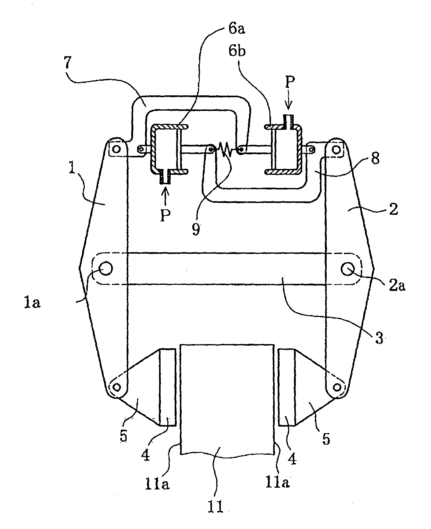
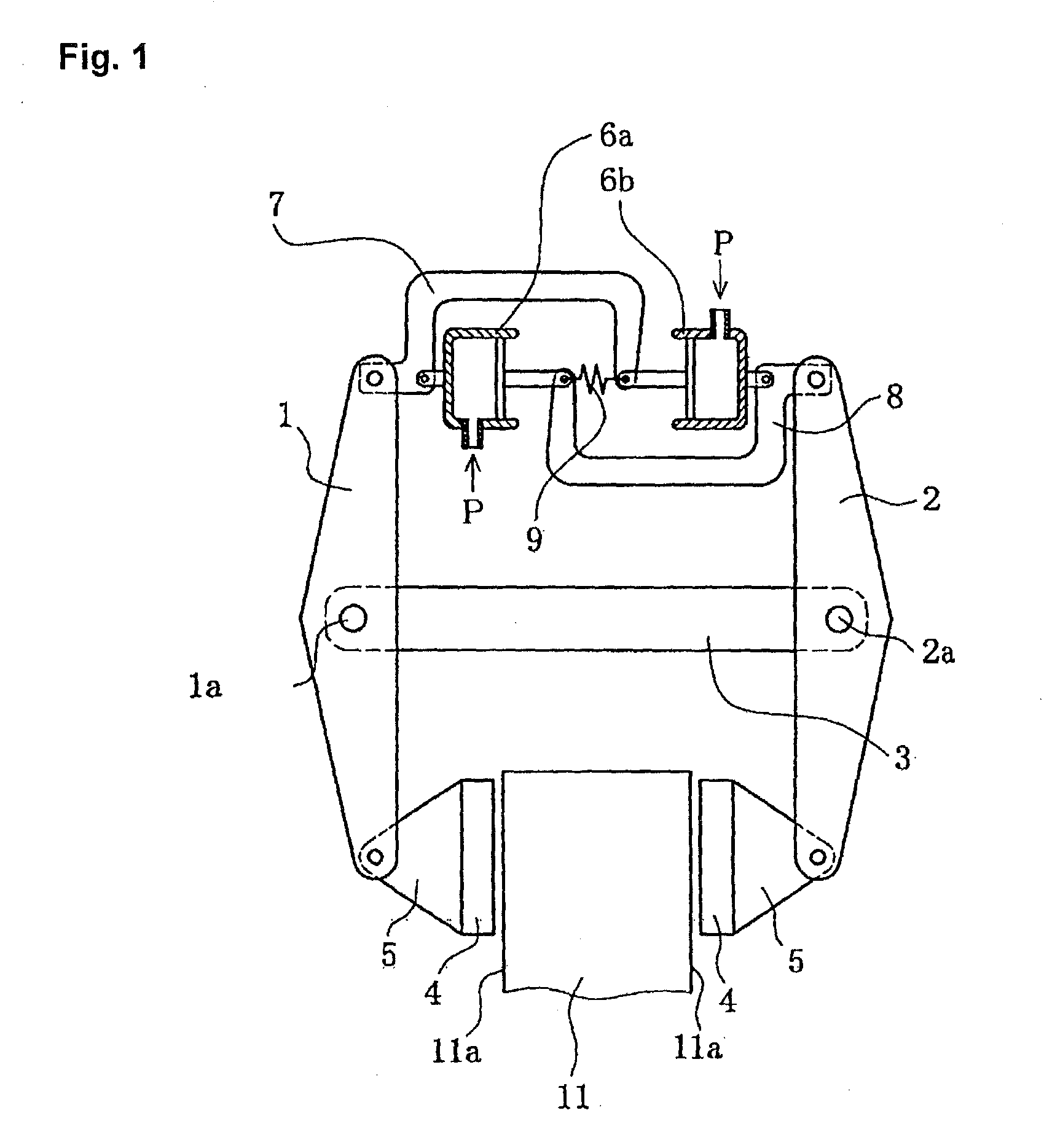
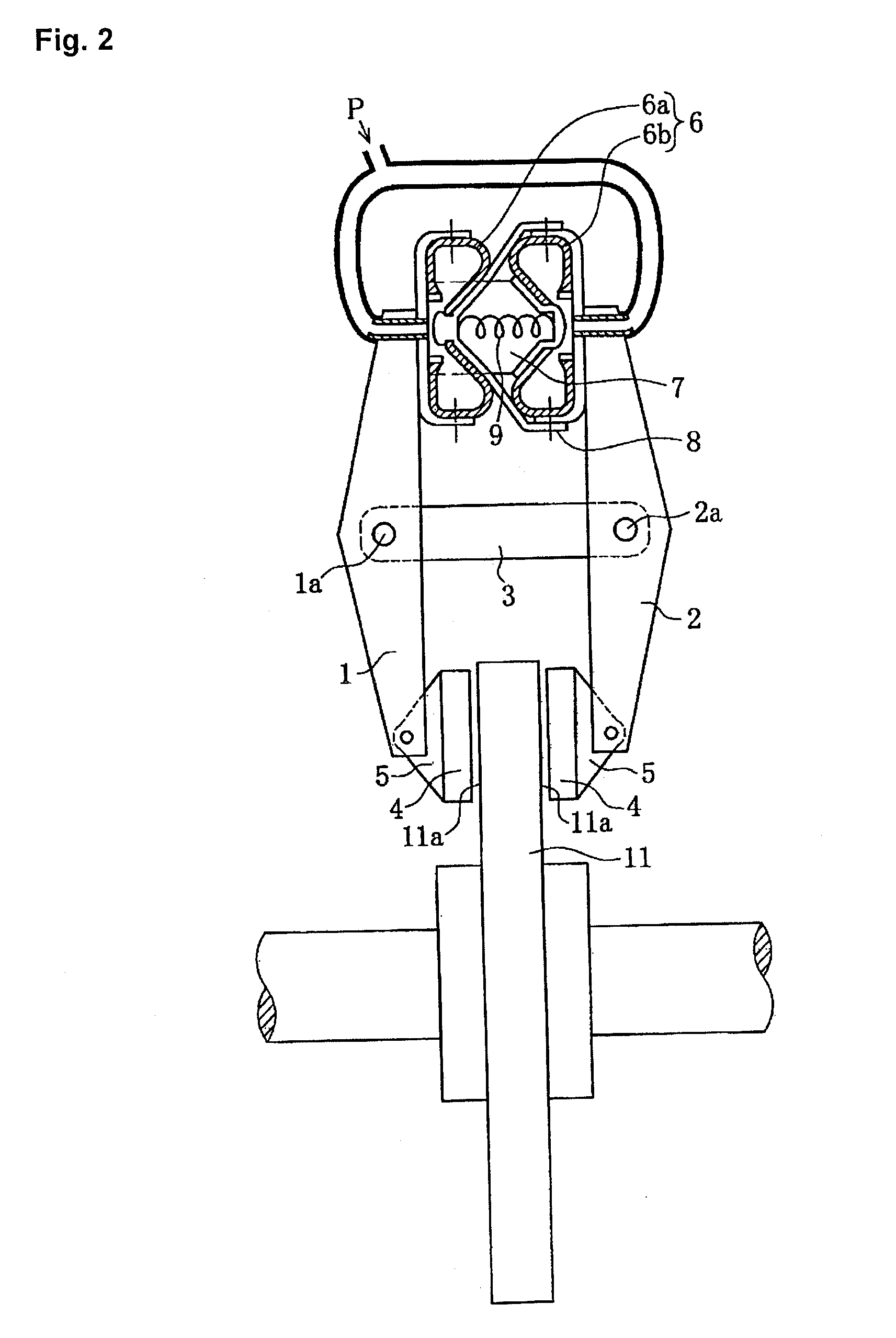
[0021]FIG. 1 is a view showing a first embodiment of a disc brake device according to the present invention, and FIG. 2 is a view showing a second embodiment of a disc brake device according to the present invention.

[0022]In FIG. 1 and FIG. 2, 1 is a first brake lever and 2 is a second brake lever. They are mounted in their mid portions on a fulcrum linking member 3 so that the brake levers can pivot. A brake head 5 on which a brake pad 4 is mounted is pivotably installed on one end of each brake lever, and a brake cylinder 6 which is extended or contracted by pneumatic pressure is mounted between the other ends of the brake levers. The two brake pads 4 which are mounted on the brake levers through the brake heads...


PUM


Abstract

A pneumatic disc brake device for a railway rolling stock which can produce two times the conventional braking force when the brake cylinder diameter is the same comprises first and second brake levers (1, 2), a pair of brake pads (4) which are mounted through brake heads (5) at one end of the brake levers so as to oppose to a brake disc, and a brake cylinder (6) disposed between the other ends of the first and second brake levers, wherein the brake cylinder (6) comprises a first cylinder part (6a) and a second cylinder part (6b) disposed in series.

Description

TECHNICAL FIELD[0001]This invention relates to a pneumatic disc brake device used on a railway rolling stock. A disc brake device according to the present invention can generate a larger braking force than a conventional device.BACKGROUND ART[0002]By decreasing the size of a pneumatic disc brake device (caliper brake device) used on a railway rolling stock, it is possible to reduce the overall aerodynamic resistance of a railway rolling stock by decreasing the weight and installation space of the brake device. For this reason, there is a great need for reductions in the size of a brake device particularly for high speed railway rolling stocks.[0003]As shown in FIG. 9 of Patent Document 1 (JP 2008-296756 A) (that figure being attached hereto as FIG. 3), a conventional pneumatic disc brake device for a railway rolling stock has a pair of brake levers 22 and a pair of brake pads 24 disposed on both sides of a brake disc 25. Each of the brake pads is mounted on a brake head 23 which is ...

Claims


Application Information

Patent Timeline
Patent Type & Authority Applications(United States)
IPC IPC(8): B61H1/00F16D65/18
CPCB61H5/00F16D2121/02F16D55/2245F16D55/224F16D65/18
Inventor SATO, YOSHI
Owner NIPPON STEEL CORP
Why Eureka
Try Eureka