
Vehicle brake device

a technology for brake devices and vehicles, applied in the direction of brake action initiation, foot actuation initiation, vehicle components, etc., can solve the problems of increasing the cost of sensors and the inefficiency of normal brake systems without failure, and achieve the effect of increasing the cos

Active Publication Date: 2017-05-23
TOYOTA JIDOSHA KK
View PDF17 Cites 0 Cited by
  • Summary
  • Abstract
  • Description
  • Claims
  • Application Information

AI Technical Summary

Benefits of technology

The patent describes a brake system for a vehicle that uses various sensors to determine if there is a failure in one of the brake systems. The system can then efficiently use the other brake systems to transmit hydraulic pressure to the wheel cylinders, generating appropriate braking forces on the wheels. This allows for appropriate braking forces for the front and rear wheels without causing a useless change in vehicle behavior. The system can accurately determine which brake system has failed using an affordable sensor configuration. Overall, the patent is about a brake system that can quickly and accurately detect and address failures, ensuring safe and effective braking performance.

Problems solved by technology

However, the normal brake system without any failure may not be efficiently used in the related-art brake control device and brake systems which are not configured to identify the failed brake system.
However, in this case, an increase in cost caused by the provision of the sensors is concerned.

Method used


Image

  • Vehicle brake device
  • Vehicle brake device
  • Vehicle brake device

Examples


Embodiment Construction

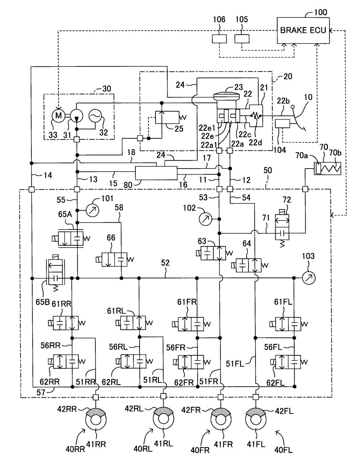
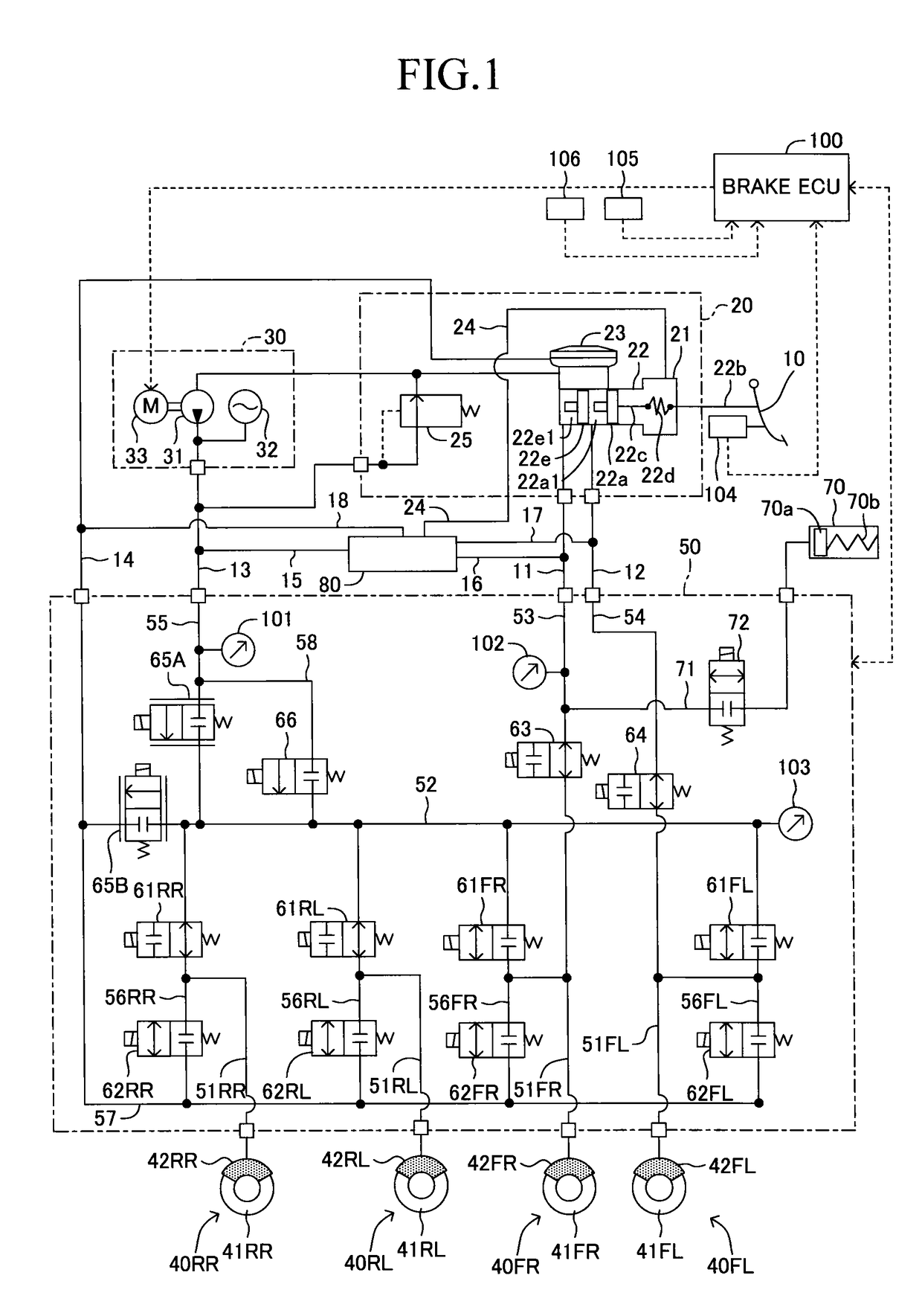
[0039]Now, a vehicle brake device according to an embodiment of the present invention is described referring to the drawings. FIG. 1 is a schematic system diagram of the vehicle brake device according to this embodiment.

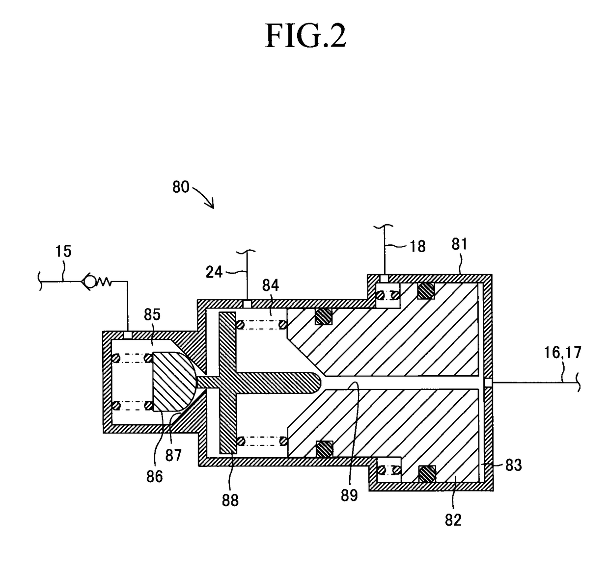
[0040]The brake device according to this embodiment includes a brake pedal 10, a master cylinder unit 20, a power hydraulic pressure generation device 30, a hydraulic pressure control valve device 50, a pressure increasing mechanism 80, and a brake ECU 100 for brake control. Brake units 40FR, 40FL, 40RR, and 40RL installed on respective wheels include brake rotors 41FR, 41FL, 41RR, and 41RL, and wheel cylinders 42FR, 42FL, 42RR, and 42RL integrated into brake calipers. The brake units 40 are not limited to the case where disk brakes are installed on all the four wheels, and, for example, drum brakes may be installed on all the four wheels, or the disk brakes and the drum brakes may be arbitrarily combined in such a way that the disk brakes are installed on the front ...


PUM


Abstract

A brake ECU brings master cut valves into an open state and brings holding valves into a closed state, thereby controlling a master cylinder and wheel cylinders to communicate to each other when a magnitude of a hydraulic pressure detected by an accumulator pressure sensor has decreased to a value less than a predetermined value set in advance. On the other hand, the ECU maintains holding valves in an open state, and controls an accumulator and the wheel cylinders to communicate to each other via linear control valves. Then, the ECU determines in which brake system a failure occurs out of a brake system for a front right wheel, a brake system for a front left wheel, and brake systems for rear right and left wheels based on changes in hydraulic pressure detected by a sensor, a master cylinder pressure sensor, and a control pressure sensor.

Description

TECHNICAL FIELD[0001]The present invention relates to a vehicle brake device including a pressurizing pump and a linear control valve, and being configured to set a target hydraulic pressure for wheel cylinders corresponding to a hydraulic pressure that is generated in a master cylinder in response to a stepping operation by a driver on a brake pedal, and drive the linear control valve, thereby supplying the hydraulic pressure increased by the pressurizing pump so that the hydraulic pressure follows the set target hydraulic pressure for the wheel cylinders.BACKGROUND ART[0002]Hitherto, as the vehicle brake device of this type, a brake control device disclosed in, for example, Patent Literature 1 has been known. In the related-art brake control device, in a state where a pressure increasing linear control valve and a pressure decreasing linear control valve are driven to supply a hydraulic pressure increased by a pressurizing pump so that the hydraulic pressure follows a set target h...

Claims


Application Information

Patent Timeline
Patent Type & Authority Patents(United States)
IPC IPC(8): B60T8/88B60T7/04B60T13/68B60T8/40B60T13/66B60T13/14B60T13/74
CPCB60T13/686B60T7/042B60T8/4081B60T8/88B60T13/142B60T13/146B60T13/662
Inventor YAMASAKI, TSUYOSHIOHKUBO, MASAYASU
Owner TOYOTA JIDOSHA KK
Learn More