Brake system

a technology of brake system and braking force, which is applied in the direction of braking system, mechanically actuated brake, actuator, etc., can solve the problems of inability to obtain predetermined braking force and small torque constant at high temperatures, and achieve the effect of generating appropriate braking for

Active Publication Date: 2016-02-25
HITACHI ASTEMO LTD
View PDF5 Cites 3 Cited by
  • Summary
  • Abstract
  • Description
  • Claims
  • Application Information

AI Technical Summary

Benefits of technology

[0008]According to the present invention, it is possible to provide an electric power brake that can generate appropriate braking force even when temperature is changed.

Problems solved by technology

However, a torque constant becomes small at high temperatures.
Thus, if the set current value is merely changed proportional to the atmosphere temperature, there is a possibility that the predetermined braking force cannot be obtained.

Method used


Image

  • Brake system
  • Brake system
  • Brake system

Examples


first embodiment

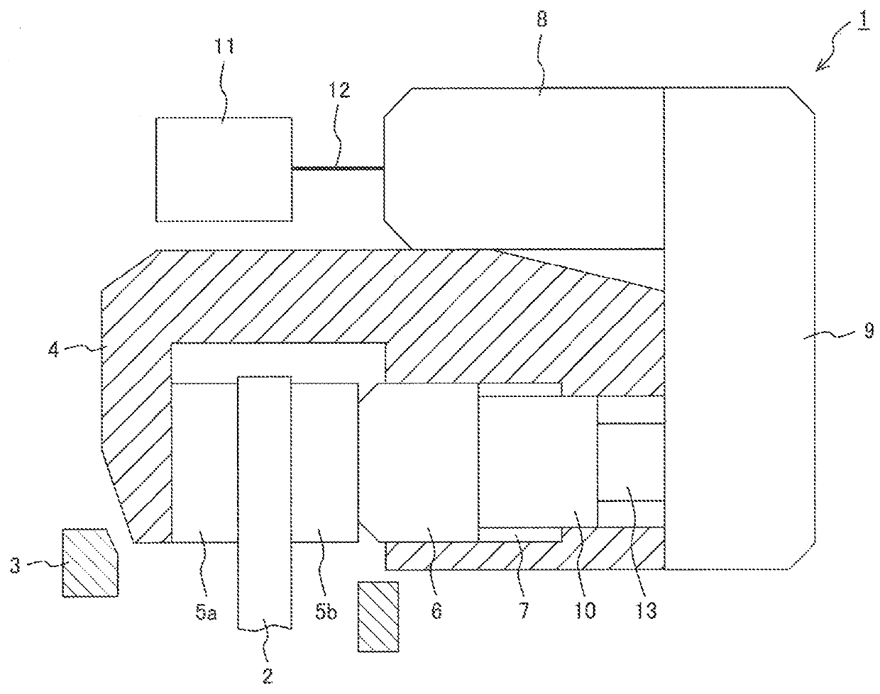
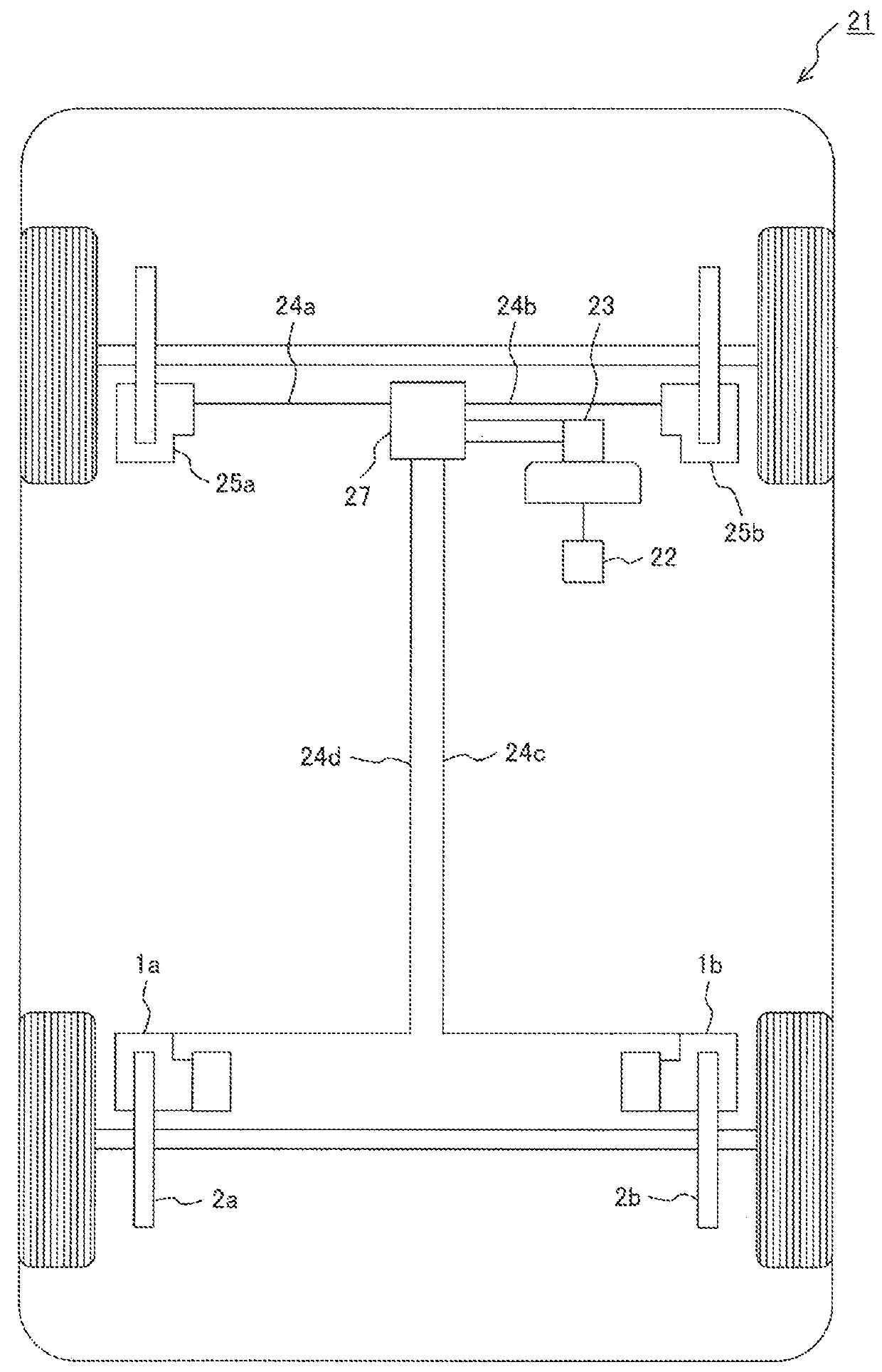
[0023]First, a first embodiment of a brake system according to the present invention will be described using FIG. 1 to FIG. 8. FIG. 1 is a configuration diagram for showing an example of the brake system to which the present invention is applied, and FIG. 2 is a diagram for showing a configuration example of a vehicle having the brake system.

[0024]As shown in FIG. 2, the present invention is applied to disc brake systems 1a and 1b (the configurations of the systems 1a and 1b are the same) which are disposed at right and left rear wheel parts of a vehicle 21. In addition to the disc brake systems 1a and 1b of the rear wheels, the vehicle 21 includes: a brake pedal 22 that is operated by a driver; a master cylinder 23 having a vacuum boosting system that applies pressure to brake fluid while moving an internal piston by operating the brake pedal 22; pipes 24a, 24b, 24c, and 24d that transmit pressure; and disc brake systems 25a and 25b (the configurations of the systems 25a and 25b ar...

second embodiment

[0045]Next, a second embodiment of a brake system according to the present invention will be described using FIG. 10. It should be noted that only the method of setting the motor stopping current 44 is changed in the second embodiment. Thus, constitutional elements having the same configurations and functions as those of the disc brake system 1 already described using FIG. 1 to FIG. 9 are given the same reference numerals below, and thus the concrete explanation will not be repeated.

[0046]FIG. 10 shows a relation between the idle running current 45 and the motor stopping current 44 in the second embodiment. As shown in FIG. 10, the relation between the idle running current 45 and the motor stopping current 44 is changed in accordance with voltage. Voltage maps of three patterns are provided in the drawing, and may be interpolated using a predetermined function.

[0047]For example, in the case where the motor 8 is stopped when the motor current 43 has exceeded the motor stopping curren...

third embodiment

[0049]Next, a third embodiment of a brake system according to the present invention will be described using FIG. 11.

[0050]It should be noted that only the method of setting the motor stopping current 44 is changed in the third embodiment. Thus, constitutional elements having the same configurations and functions as those of the disc brake system 1 already described using FIG. 1 to FIG. 9 are given the same reference numerals below, and thus the concrete explanation will not be repeated.

[0051]FIG. 11 is a diagram for explaining a method of setting the motor stopping current 44. In addition to the difference of voltage in the second embodiment, the motor stopping current 44 is changed depending on the required braking force in the third embodiment. The required braking force is changed depending on the inclination of roads, or the like in some cases. Therefore, these relations are obtained for each required braking force, and thus the excessive braking force can be suppressed relative...


PUM


Abstract

An object of the present invention is to obtain a brake system that can generate appropriate braking force without influence of temperature. A brake system includes: a piston that presses pressing members; a motor that moves the piston; a current detection unit that detects current flowing in the motor; a storage unit that stores a correspondence relation between idle running current and motor stopping current; a motor stopping current setting unit that sets the motor stopping current using the storage unit and the idle running current; and a control unit that stops to supply the current to the motor when the current flowing in the motor reaches the motor stopping current. The correspondence relation is set so that the rate of change of the motor stopping current relative to the idle running current becomes smaller when the idle running current is small than that when it is large.

Description

CLAIM OF PRIORITY[0001]The present application claims priority from Japanese Patent application serial No. 2014-170299, filed on Aug. 25, 2014, the content of which is hereby incorporated by reference into this application.FIELD OF THE INVENTION[0002]The present invention relates to a brake system used for braking a vehicle.BACKGROUND OF THE INVENTION[0003]An electric power brake that brakes a vehicle by pressing pressing members such as brake pads or drum shoes to a rotary member such as a rotor or a brake drum using the rotation of a motor has been proposed as a brake system from the past. There is a need for the electric power brake to minimize braking force that exceeds the required braking force.[0004]Japanese Unexamined Patent Application Publication No. 2008-56090 describes that the atmosphere temperature is detected to change a set current value proportional to the atmosphere temperature because the load applied to an actuator is increased at low temperatures and predetermin...

Claims


Application Information

Patent Timeline
Patent Type & Authority Applications(United States)
IPC IPC(8): B60T8/171B60T8/17F16D55/225F16D65/18
CPCB60T8/171F16D55/225F16D2121/24B60T8/17F16D65/18B60T13/745B60T13/741F16D55/226
Inventor SETO, SHINJIKOBUNE, TATSUROSAKASHITA, TAKAYASU
Owner HITACHI ASTEMO LTD
Why Eureka
Try Eureka