
Zero Torque Membrane Seal

a membrane seal and zero-torque technology, applied in the direction of engine seals, mechanical equipment, engine components, etc., can solve the problems of adding torque load and cost to the seal design, affecting the performance of the system, etc., to prevent grease loss, add torque load, and hinder the system's performance

Active Publication Date: 2012-03-22
FREUDENBERG NOK GEN PARTNERSHIP
View PDF10 Cites 8 Cited by
  • Summary
  • Abstract
  • Description
  • Claims
  • Application Information

AI Technical Summary

Benefits of technology

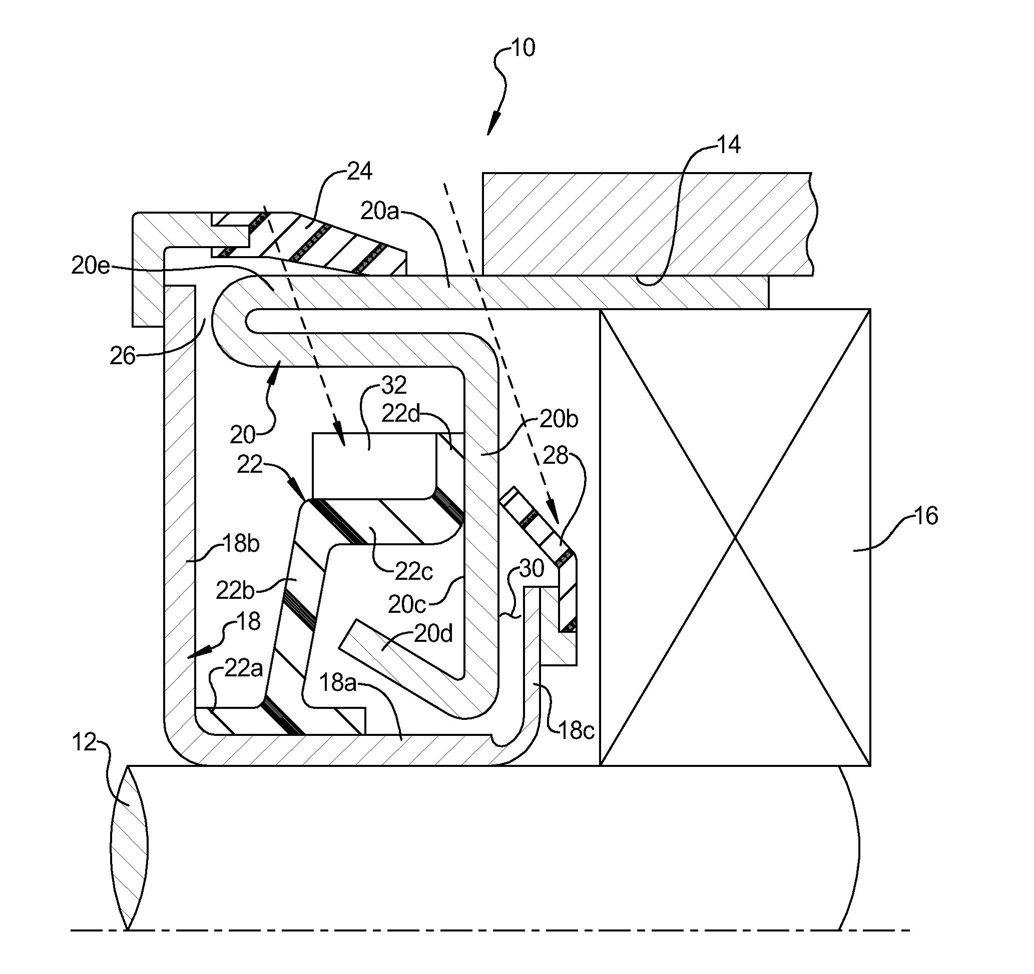
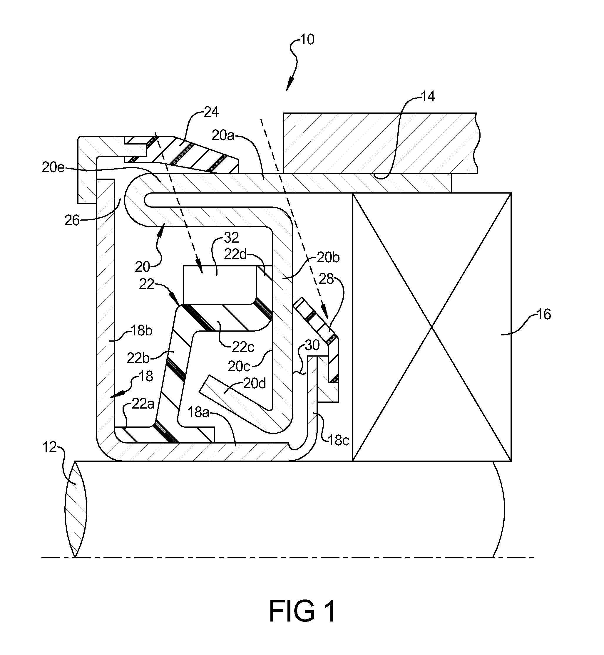
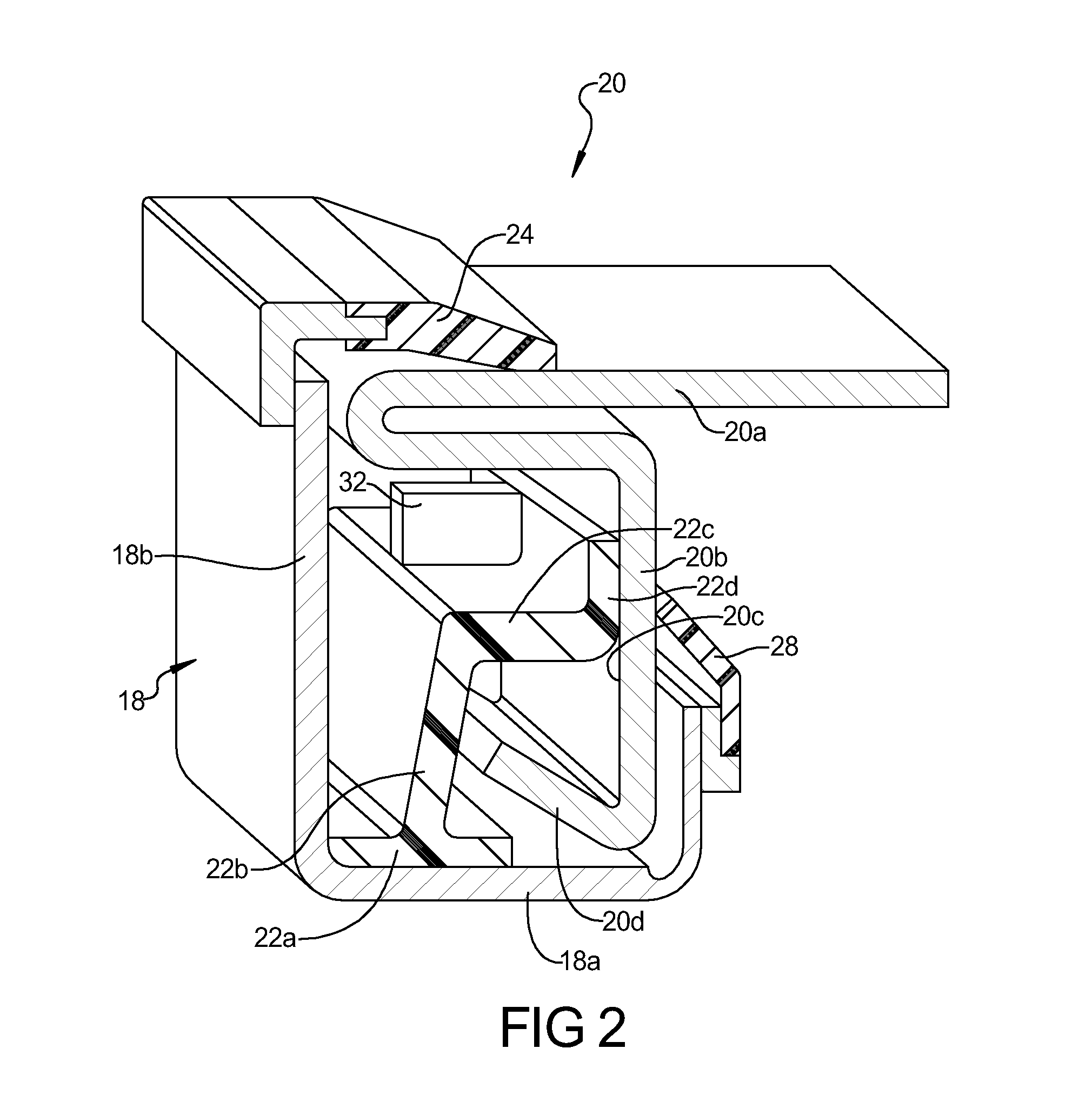
The present disclosure relates to a zero torque membrane seal assembly for sealing between a rotating shaft and a bore. The seal assembly includes an inner case and an outer case that are mounted on the shaft and the bore, respectively. A membrane extends from the base of the inner case and seals with the outer case. The seal assembly is designed to prevent water and dirt from entering the system and to prevent grease loss. The seal assembly has low or zero friction with the rotating shaft, reducing the amount of torque load and improving performance. The technical effect of the invention is to provide a seal assembly that reduces friction and torque load while still effectively sealing the space between the shaft and the bore.

Problems solved by technology

The amount of torque that a seal applies to a rotating shaft system is a parasitic loss that can hinder the system's performance.
However, the conventional dynamic seals can have torque loads of generally 30 pound-inches or larger.
The conventional dynamic seals can often require a garter spring to apply added forces to the seal lip which adds torque load as well as added cost to the seal design.

Method used


Image

  • Zero Torque Membrane Seal
  • Zero Torque Membrane Seal
  • Zero Torque Membrane Seal

Examples


Embodiment Construction

[0016]Example embodiments will now be described more fully with reference to the accompanying drawings.

[0017]Example embodiments are provided so that this disclosure will be thorough, and will fully convey the scope to those who are skilled in the art. Numerous specific details are set forth such as examples of specific components, devices, and methods, to provide a thorough understanding of embodiments of the present disclosure. It will be apparent to those skilled in the art that specific details need not be employed, that example embodiments may be embodied in many different forms and that neither should be construed to limit the scope of the disclosure.

[0018]The terminology used herein is for the purpose of describing particular example embodiments only and is not intended to be limiting. As used herein, the singular forms “a”, “an,” and “the” may be intended to include the plural forms as well, unless the context clearly indicates otherwise. The terms “comprises,”“comprising,”“...


PUM


Abstract

A low friction seal for sealing between a shaft and a bore and includes an inner case adapted to be mounted on the shaft. An outer case is adapted to be mounted within the bore. A seal element is mounted to the inner case and includes a base portion attached to the inner case. A membrane extends from the base portion and an axially extending leg extends from the membrane. A seal lip extends from the axially extending leg and sealingly engages a radially extending portion of the outer case. As the shaft rotates, the centrifugal forces tend to cause the membrane to flex and the torque loads applied by the dynamic seal are reduced to the point that the seal lip can lift off and apply zero torque load.

Description

FIELD[0001]The present disclosure relates to a zero torque membrane seal having reduced friction with seal lift off at high rotational speeds.BACKGROUND AND SUMMARY[0002]This section provides background information related to the present disclosure which is not necessarily prior art.[0003]Dynamic seals are commonly used in combination with bearings to prevent water and dirt ingress from the outside environment into the bearing. The seal is also used to prevent grease loss from a bearing to the outside. The amount of torque that a seal applies to a rotating shaft system is a parasitic loss that can hinder the system's performance. Therefore, the amount of torque load applied by a dynamic seal is balanced with the seal's capability to adequately perform its sealing function.[0004]Conventional dynamic seal designs have proven to adequately perform the function of preventing water and dirt ingress. However, the conventional dynamic seals can have torque loads of generally 30 pound-inche...

Claims


Application Information

Patent Timeline
Patent Type & Authority Applications(United States)
IPC IPC(8): F16J15/32
CPCF16J15/164F16J15/3456F16J15/3256
Inventor BERDICHEVSKY, ALEXANDERSAKATA, DAVIDJIANG, JIANBIN
Owner FREUDENBERG NOK GEN PARTNERSHIP
Learn More