Control device for electric rotating machine

Inactive Publication Date: 2012-03-22
DENSO CORP
View PDF3 Cites 24 Cited by
  • Summary
  • Abstract
  • Description
  • Claims
  • Application Information

AI Technical Summary

Benefits of technology

[0013]Accordingly, even when the ringing is generated in the controlled variable or the physical quantity of the electric rotating machine, the controlled variable or the physical quantity can be pr

Problems solved by technology

When the operating state of the inverter is switched to another one every changing period, it is well known that ringing occurs generally in the current actually flowing through the three-phase motor.
Therefore, when the detec

Method used


Image

  • Control device for electric rotating machine
  • Control device for electric rotating machine
  • Control device for electric rotating machine

Examples


first embodiment

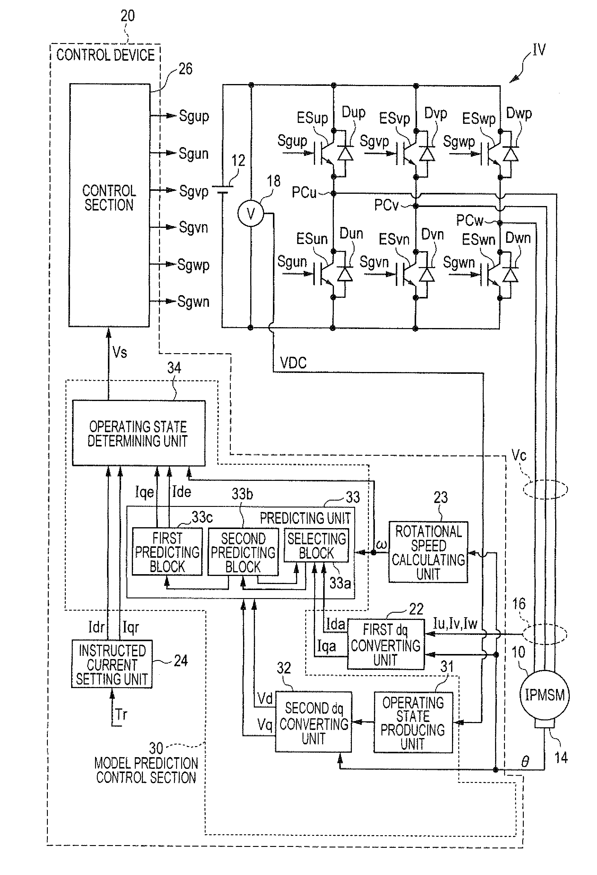
[0027]FIG. 1 is a view showing the structure of a control system having a control device for an electric rotating machine according to the first embodiment. As shown in FIG. 1, a control system has a high voltage battery 12 outputting electric power of a high direct current (dc) voltage as a direct current power source, an inverter IV set in one of various operating states to convert the power of the battery 12 into electric power of a three-phase alternating current (ac) voltage corresponding to the operating state, a motor generator 10 receiving the power through the inverter IV as an electric rotating machine to generate a torque (or a rotational force), and a control device 20 for receiving a target torque Tr, receiving detection values from various sensors detecting specific controlled variables of the motor generator 10 or physical values by which values of the specific controlled variables can be calculated, and adjusting a change of the operating state of the inverter IV acc...

second embodiment

[0103]FIG. 10 is a view showing the structure of a control system having a control device 20A according to the second embodiment. As shown in FIG. 10, a control system has the battery 12, the inverter IV, the generator 10, and a control device 20A for receiving a target torque Tr, receiving detection values from the sensors 14 and 16 or physical values, and determining an operating state of the inverter IV such that the generator 10 appropriately generates a torque matching with the target torque Tr.

[0104]In this embodiment, a torque generated in the generator 10 and a magnetic flux induced in the generator 10 are set as controlled variable. An alternating current flowing through the generator 10 to generate and induce the torque and the magnetic flux in the generator 10 is set as a physical quantity. The control variable can be determined from the physical quantity. The control device 20A directly controls the current (i.e., the physical value) of the generator 10 to adjust the tor...


PUM


Abstract

A control device has a predicting unit for predicting a first current flowing through a motor in a next control period, at a predicting time during a predetermined period after a change of switching state in an inverter by using a current detected before the change and for predicting a second current of a control period later than the next control period by one control period by using the predicted first current, a determining unit for determining a next operating state of the inverter by using the predicted second current and an instructed value so as to reduce a change of switching state in the change of the operating state, and a control unit for controlling the inverter to be set in the determined operating state in the next control period and controlling the current of the motor depending on the operating state of the inverter.

Description

CROSS-REFERENCE TO RELATED APPLICATION[0001]This application is based upon and claims the benefit of priority of the prior Japanese Patent Application 2010-210481 filed on Sep. 21, 2010, so that the contents of which are incorporated herein by reference.BACKGROUND OF THE INVENTION[0002]1. Field of the Invention[0003]The present invention relates generally to a control device which controls switching elements of an electric power inverter circuit having connecting points, being connected with respective terminals of an electric rotating machine and being set at respective electric potentials different from one another, by changing an on (i.e., conductive) or off (i.e., non-conductive) state of selected switching elements to the off or on state and which controls a controlled variable of the electric rotating machine connected with the connecting points of the electric power inverter circuit.[0004]The present invention relates more particularly to the control device which has a predic...

Claims


Application Information

Patent Timeline
IPC IPC(8): H02P21/14H02P27/04H02P21/00H02P21/13H02P21/18H02P21/22H02P21/24H02P23/07H02P23/14H02P27/08
CPCH02P21/13H02P21/0017
Inventor IMURA, AKIHIRO
Owner DENSO CORP
Why Eureka
Try Eureka