
Eureka
For R&D, Eureka makes reading and utilizing patents & technical documents easy.
Eureka AIR
Designed for self-driven R&D workflows. Generate viable solutions, solve complex R&D challenges, empower your innovation with AI.

Eureka Materials
Designed for material experts only. Revolutionize your material R&D, from search, analyze, to developing new materials.

TechResearch
Generate reliable direction feasibility study reports for your R&D in just a few steps.

TechSeek
Discover and master advanced knowledge NOW. Basics, ideas, possibilities, all at once.

TechMind
As an expert in R&D Theories, TechMind can generates customized viable solutions instantly.

TechRisk
Analyze your overall solution with one click, know your potential R&D risks in advance.

TechMonitor
Get weekly tech updates, stay abreast of the latest tech innovations and key insights.
Multi-Frequency Antenna
- Summary
- Abstract
- Description
- Claims
- Application Information
AI Technical Summary
Benefits of technology
Problems solved by technology
Method used
Image

Examples
first embodiment
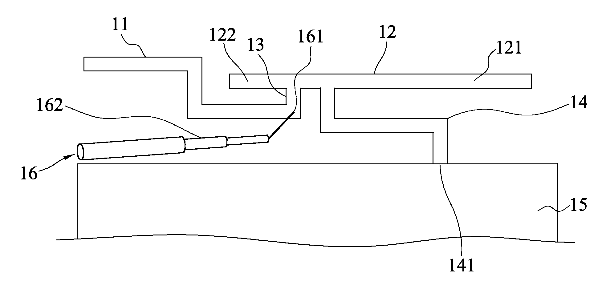
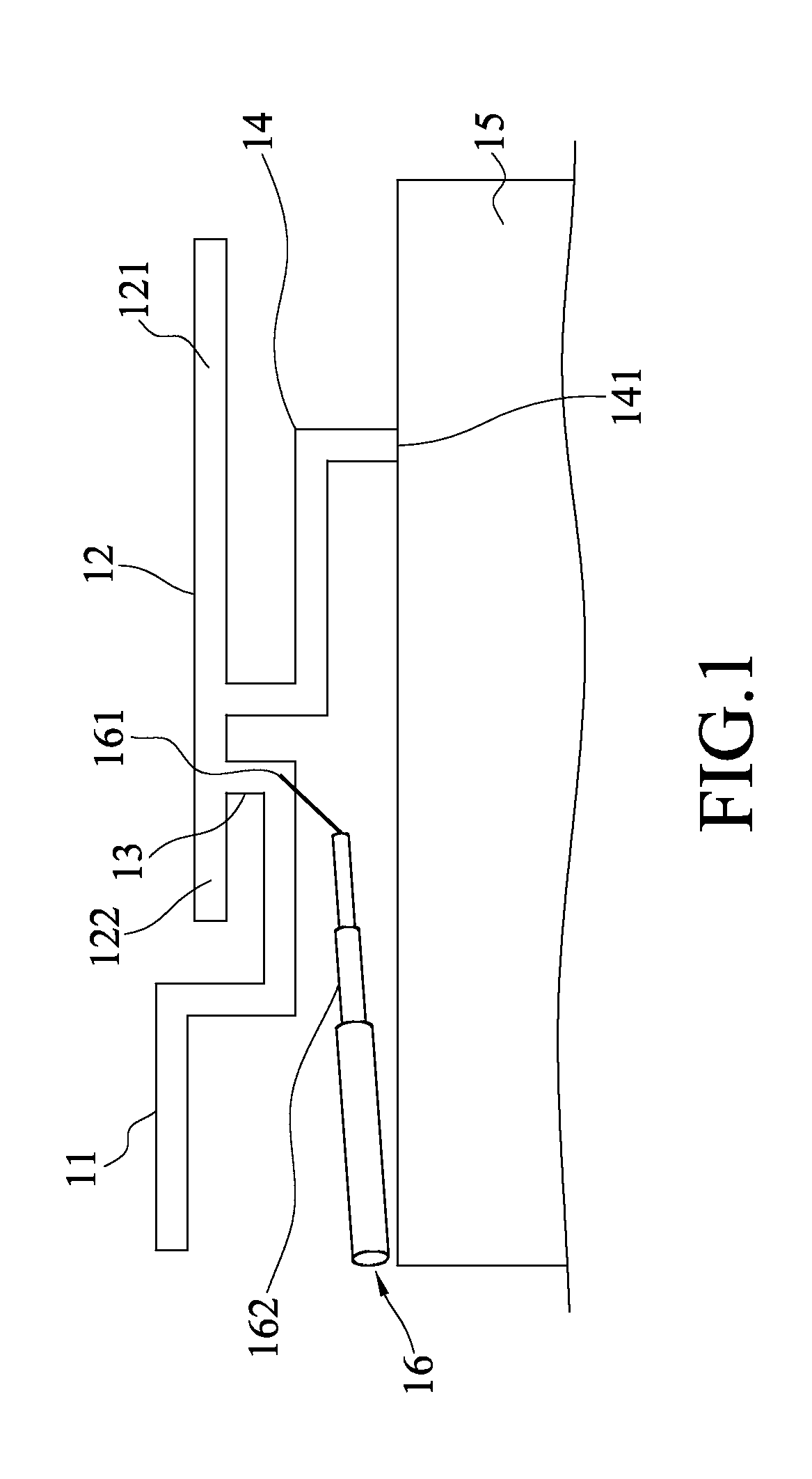
[0016]Refer to FIG. 1 a top view of a multi-frequency antenna according to the present invention. The multi-frequency antenna of the present invention comprises a first conductor 11, a second conductor 12, a feeder conductor 13, a short-circuit member 14, a grounding plane 15 and a feeder cable 16.
[0017]The first conductor 11 has a serpentine form. The second conductor 12 is parallel to the first conductor 11 and extends in one side of the first conductor 11. The feeder conductor 13 connects the first conductor 11 and the second conductor 12. The short-circuit member 14 connects with the second conductor 12 and extends serpentinely with an end 141 thereof connecting with the grounding plane 15. The short-circuit member 14 is arranged in one side of the second conductor 12 and connects with the second conductor 12 at a near-central point of the second conductor 12, which divides the second conductor 12 into a first extension 121 and a second extension 122. The feeder cable 15 include...
second embodiment
[0020]Refer to FIG. 3 a diagram showing the measurement results of the voltage standing wave ratio (VSWR) of the multi-frequency antenna according to the present invention, wherein the horizontal axis represents frequency and the vertical axis represents dB. FIG. 3 shows that the operational frequency band S1 ranges from 2.0 to 7.0 GHz, which covers the frequency bands of the WLAN 802.11b / g system (ranging from 2.4 to 2.5 GHz), the WiMAX 2.3 G system (ranging from 2.5 to 2.7 GHz), the WiMAX 3.5 G system (ranging from 3.3 to 3.8 GHz), and the WiMAX system (ranging from 4.9 to 2.825 GHz).
[0021]In the standards, an antenna is required to have VSWR lower than 3. Otherwise, the antenna would not have the required performance. FIG. 3 shows that VSWR is lower than 3 in all the frequency bands and lower than 2 in most of the frequency bands. Thus, the operating bandwidth is greatly increased. Therefore, FIG. 3 proves that the operating bandwidths of the present invention can satisfy the des...
PUM
 Abstract
Description
Claims
Application Information
 - R&D Engineer
- R&D Manager
- IP Professional
- Industry Leading Data Capabilities
- Powerful AI technology
- Patent DNA Extraction
Browse by: Latest US Patents, China's latest patents, Technical Efficacy Thesaurus, Application Domain, Technology Topic, Popular Technical Reports.
© 2024 PatSnap. All rights reserved.Legal|Privacy policy|Modern Slavery Act Transparency Statement|Sitemap|About US| Contact US: help@patsnap.com