Phased array antenna and method for producing thereof

a phased array and antenna technology, applied in the manufacture of antenna arrays, antennas, modular arrays, etc., can solve the problems of affecting the operation of the complete antenna, and affecting the reliability of the complete antenna

Inactive Publication Date: 2012-03-22
ELTA SYST LTD
View PDF4 Cites 211 Cited by
  • Summary
  • Abstract
  • Description
  • Claims
  • Application Information

AI Technical Summary

Problems solved by technology

In ESA, therefore, the distance from the power amplifier to each of the radiating elements, and configuration of the power distribution arrangement leads to a considerable loss of power.
Moreover, ESA may suffer reliability deficiency, because failure in the power amplifier may jeopardize operation of the complete antenna.
However, in modular and compact construct

Method used


Image

  • Phased array antenna and method for producing thereof
  • Phased array antenna and method for producing thereof
  • Phased array antenna and method for producing thereof

Examples


Embodiment Construction

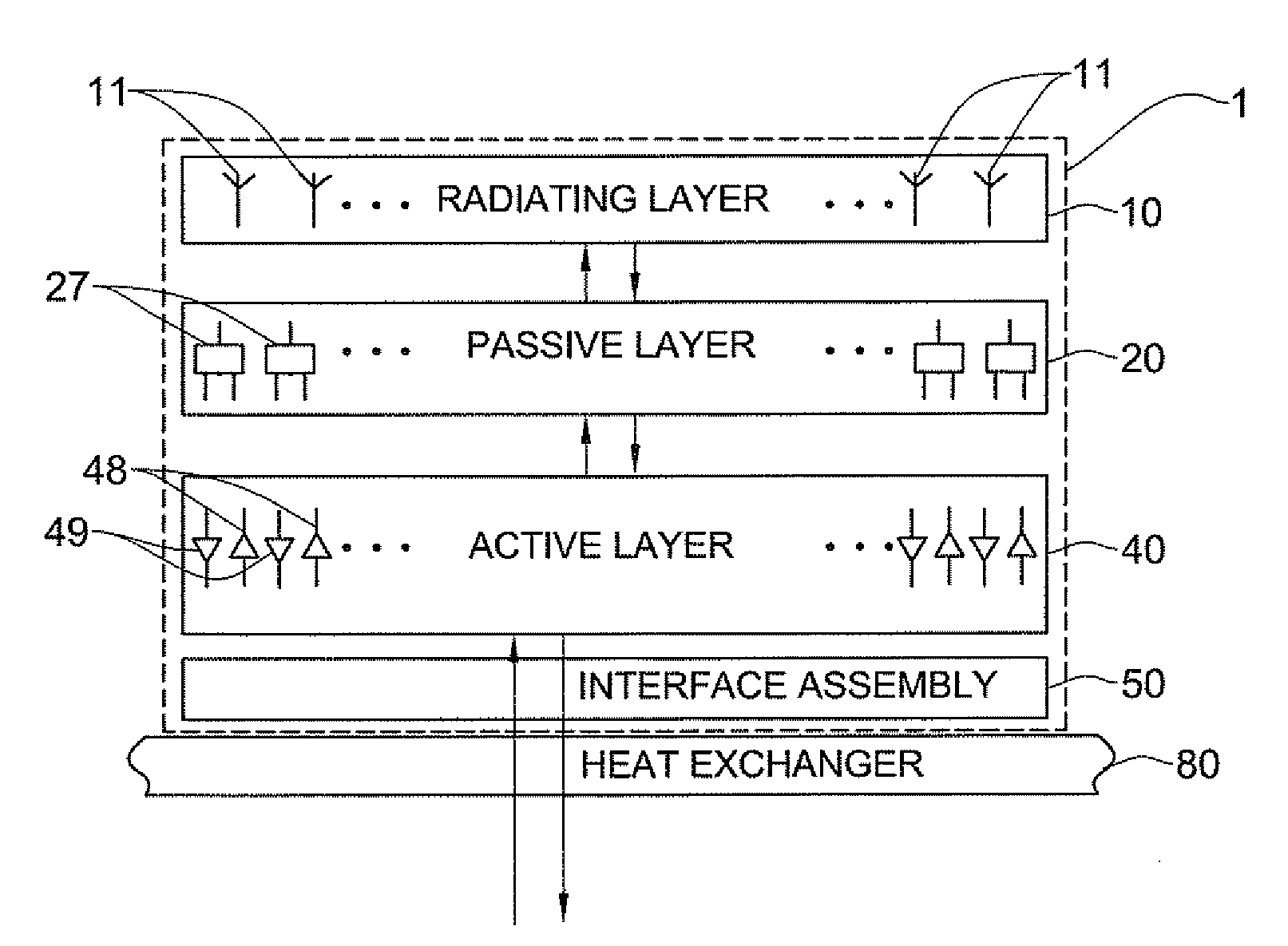
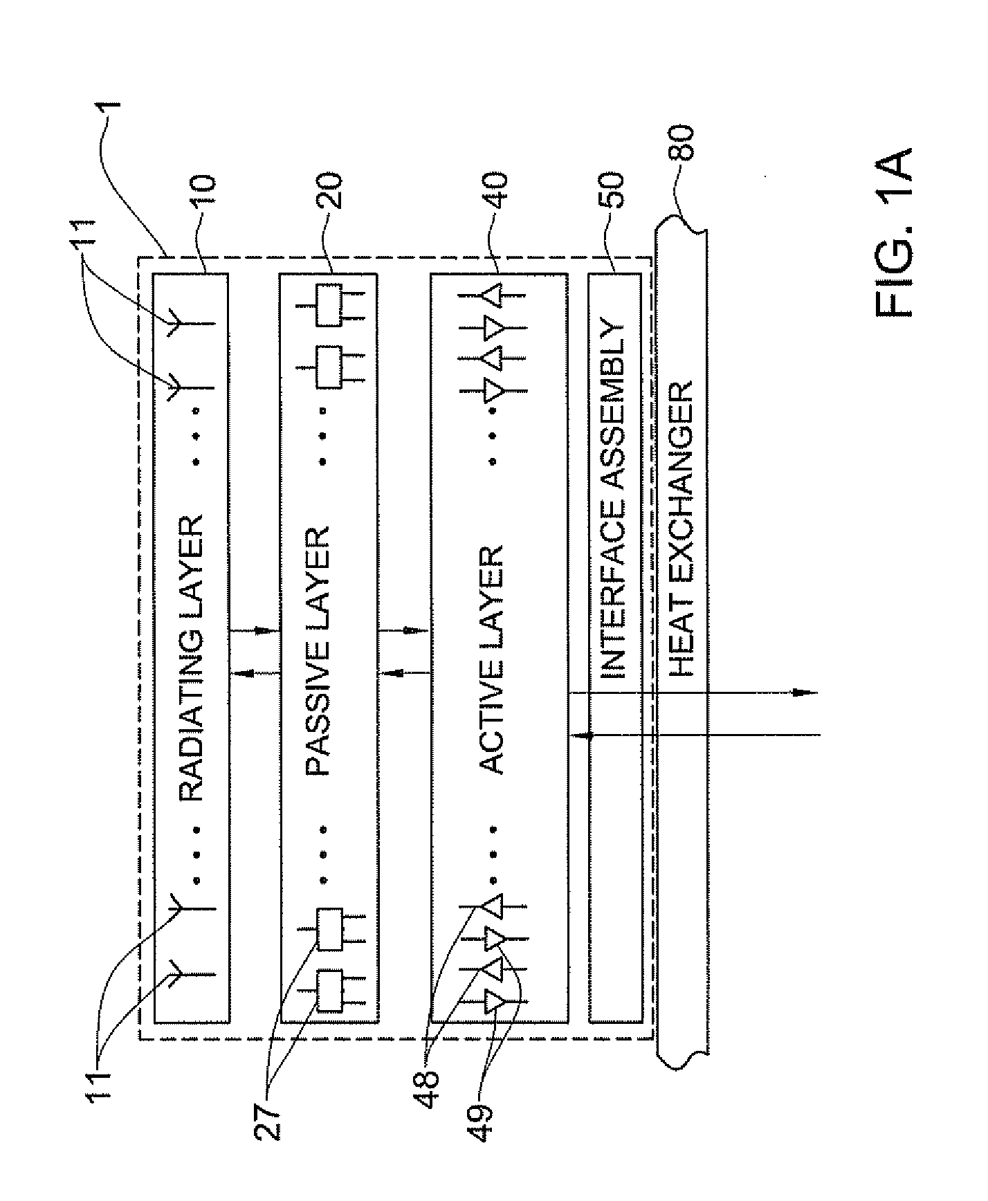
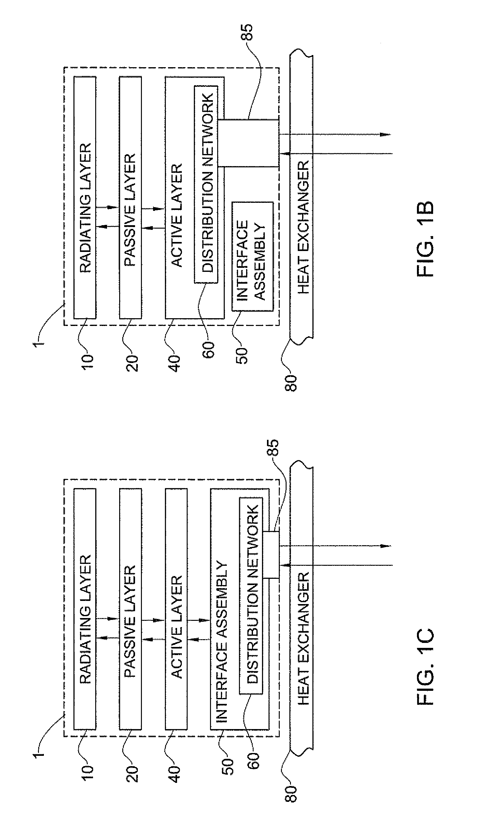
[0086]The principles and operation of a vertically stacked array antenna according to the present invention may be better understood with reference to the drawings and the accompanying description. It should be understood that these drawings are given for illustrative purposes only and are not meant to be limiting. It should be noted that the figures illustrating various examples of the system of the present invention are not to scale, and are not in proportion, for purposes of clarity. It should be noted that the blocks as well other elements in these figures are intended as functional entities only, such that the functional relationships between the entities are shown, rather than any physical connections and / or physical relationships. The same reference numerals and alphabetic characters will be utilized for identifying those components which are common in the device and its components shown in the drawings throughout the present description of the invention.

[0087]Referring to FI...


PUM

PropertyMeasurementUnit
Metallic bondaaaaaaaaaa
Distributionaaaaaaaaaa

Abstract

A vertically stacked array antenna structure is described. The structure comprises a radiating layer, a passive layer disposed under said radiating layer, an active layer disposed under said passive layer, and an interface assembly. The radiating layer comprises an array of radiating elements. The passive layer has only passive components. At least a part of the passive components includes an array of RF duplexers corresponding to the array of radiating elements. The active layer comprises RF amplifiers. The interface assembly comprises at least one metallic frame which is in direct thermal coupling with the RF amplifiers. The interface assembly is configured for providing thermal communication of the active layer with a heat exchanger.

Description

FIELD OF THE INVENTION[0001]This invention relates to a phased array antenna, and more specifically to a layered, vertically stacked antenna.BACKGROUND OF THE INVENTION[0002]Phased array antennas have presented a great leap in the progress of devices associated with electromagnetic radiation, and particularly various RADAR systems. A phased array antenna generally includes an array of radiating elements, each radiating element defines and is associated with an individual Radio-Frequency (RF) transmit / receive (T / R) channel. The term “radiating element” herein is used interchangeably with the term “antenna element”, meaning an element that is configured and operable to radiate and / or receive electromagnetic energy from space. In each such channel the phase and possibly the amplitude of the signal that passes therethrough, can be controlled individually. The proper tuning of phase and amplitude of the signal in each channel of the antenna array provides for great flexibility in the cha...

Claims


Application Information

Patent Timeline
IPC IPC(8): H01Q21/00H01P11/00
CPCH01Q21/0025Y10T29/49016H01Q21/0087
Inventor ASHER, MENACHEMTURGEMAN, MEIR
Owner ELTA SYST LTD
Why Eureka
Try Eureka