Display device

a display device and display technology, applied in non-linear optics, instruments, optics, etc., can solve the problems of difficult to control the distance between the counter electrodes, difficult to alternately time-control the application of a coloring voltage, and inability to display stablely and easily achieve a chromatic display

Inactive Publication Date: 2012-03-22
ALPS ALPINE CO LTD
View PDF1 Cites 20 Cited by
  • Summary
  • Abstract
  • Description
  • Claims
  • Application Information

AI Technical Summary

Benefits of technology

[0010]Accordingly, the present invention provides a display device that can stably and easi

Problems solved by technology

Therefore, the colored region is easily fluctuated, resulting in unstable displaying.
Furthermore, a relatively large screen causes no problem, but, in a small screen, it is believed to be quite difficult to alternately time-control the application of a coloring voltage and the application of a decolorizing voltage so that only part of the colored r

Method used


Image

  • Display device
  • Display device
  • Display device

Examples


first embodiment

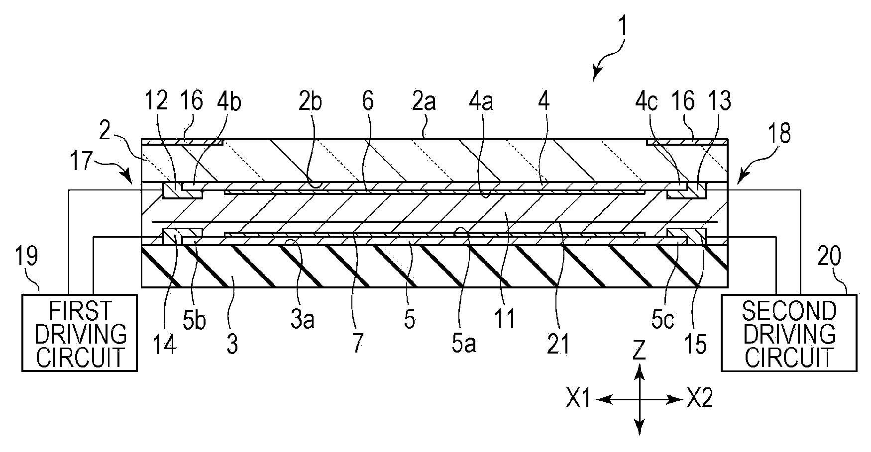
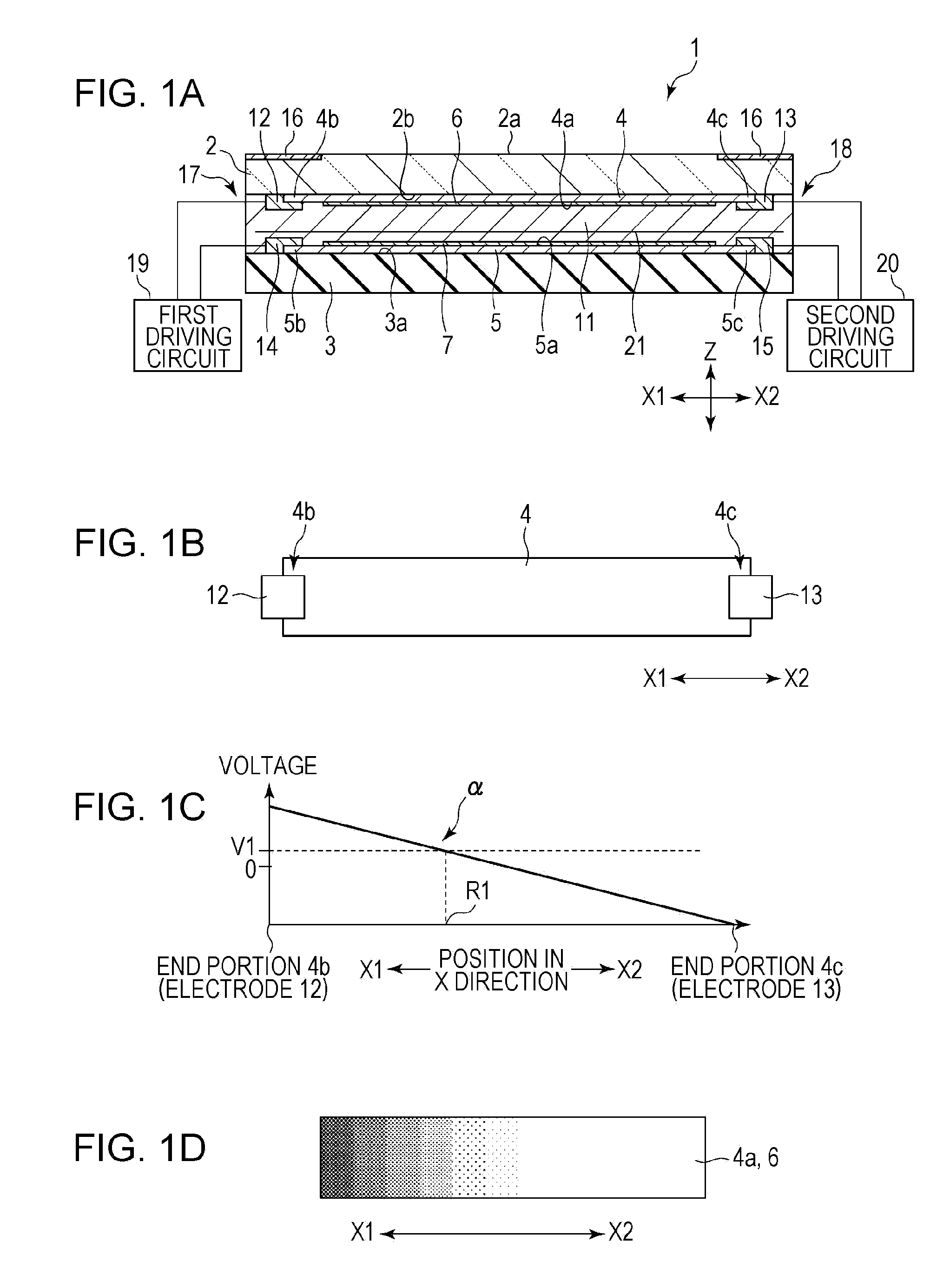
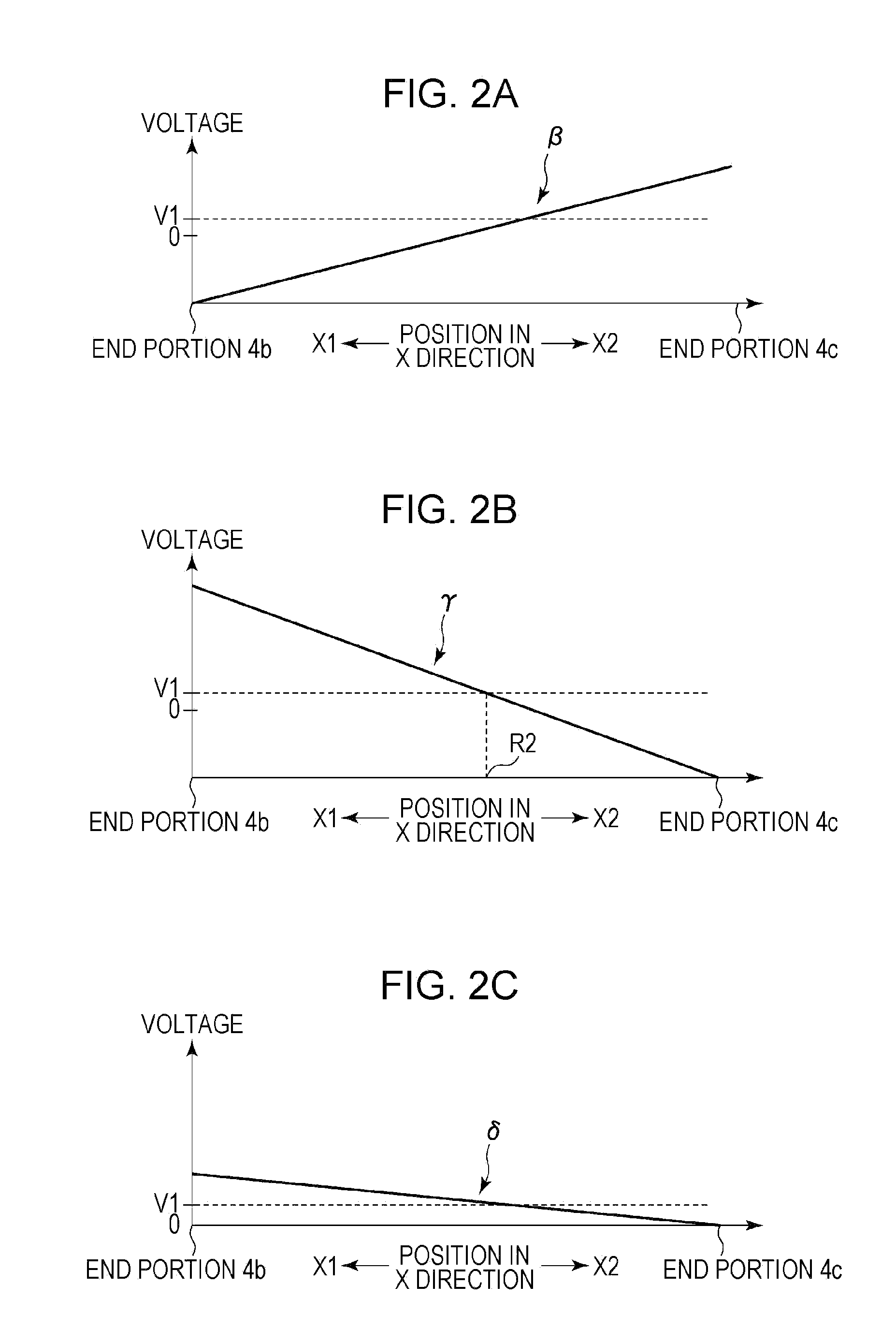
[0025]FIG. 1A is a partial longitudinal sectional view of a display device according to the present invention. FIG. 1B is a plan view of a first resistive layer and first electrodes shown in FIG. 1A. FIG. 1C is a schematic view of a distribution of voltage applied to the first resistive layer. FIG. 1D is a schematic view of a gradation display viewed from a display surface.

[0026]As shown in FIG. 1A, a first insulating substrate 2 and a second insulating substrate 3 constituting a display device 1 face each other with a space therebetween in the height (Z) direction.

[0027]The outer surface of the first insulating substrate 2 is a display surface 2a. As shown in FIG. 1A, the entire outer surface of the first insulating substrate 2 is not necessarily the display surface 2a. For example, a decorative layer 16 may be formed on the periphery of the display surface 2a. Consequently, a portion of the display surface 2a becomes translucent and a portion of the decorative layer 16 becomes opa...

second embodiment

[0066]FIG. 4 is a partial longitudinal sectional view of a display device according to the present invention. Hereinafter, in FIG. 4, the same components as those in FIG. 1A are denoted by the same reference numerals as those in FIG. 1A.

[0067]In a display device 50 shown in FIG. 4, unlike the display device 1 shown in FIG. 1A, the second resistive layer 5, the second electrochromic layer 7, and the second electrodes 14 and 15 are not disposed on the inner surface 3a of the second insulating substrate 3.

[0068]On the other hand, the configuration of the first resistive layer 4, the first electrochromic layer 6, and the first electrodes 12 and 13 disposed on the inner surface 2b of the first insulating substrate 2 is the same as that shown in FIG. 1A.

[0069]In the display device 50 shown in FIG. 4, unlike the display device 1 shown in FIG. 1A, a driving circuit 51 is connected between the first electrode 12 and the first electrode 13. A voltage is applied between the first electrodes 12...


PUM


Abstract

A display device of this embodiment includes a first insulating substrate having a display surface; a first resistive layer disposed on a surface of the first insulating substrate, the surface being opposite the display surface; a first electrochromic layer disposed on a surface of the first resistive layer; an electrolyte layer disposed on a surface of the first electrochromic layer; and a plurality of first electrodes connected to the first resistive layer. In the display device, a voltage is applied to the plurality of first electrodes so that a voltage gradient is generated in an in-plane direction of the first resistive layer.

Description

CLAIM OF PRIORITY[0001]This application claims benefit of Japanese Patent Application No. 2010-208850 filed on Sep. 17, 2010, which is hereby incorporated by reference.BACKGROUND OF THE INVENTION[0002]1. Field of the Invention[0003]The present invention relates to a display device including an electrochromic layer.[0004]2. Description of the Related Art[0005]Display devices utilizing electrochromism in which color changes through an electrochemical oxidation-reduction reaction have been known. In such display devices utilizing electrochromism, long-duration display at low voltage, long life, and the like can be expected.[0006]For example, Japanese Unexamined Patent Application Publication No. 1-277825 (Patent Document 1) discloses an invention of an electrochromic light controlling plate in which counter electrodes (resistive films) and coloring films are disposed on inner surfaces of substrates facing each other and a space between the coloring films is filled with an electrolyte.[...

Claims


Application Information

Patent Timeline
IPC IPC(8): G02F1/155
CPCG02F1/155G02F2001/1536G02F1/1533G02F1/153
Inventor SUZUKI, KATSUTOSHI
Owner ALPS ALPINE CO LTD
Why Eureka
Try Eureka