Battery pack with cooling passage

a battery cell and cooling passage technology, applied in the field of battery packs, can solve the problems of reducing the heat transfer coefficient between the air and the battery cell, degrading the cooling performance, and difficult to evenly cool the surface of the battery cell, so as to achieve effective and evenly cooled, improve the heat transfer coefficient of the cooling medium, and improve the boundary layer of the cooling medium.

Active Publication Date: 2012-03-22
DENSO CORP
View PDF6 Cites 21 Cited by
  • Summary
  • Abstract
  • Description
  • Claims
  • Application Information

AI Technical Summary

Benefits of technology

[0010]In this way, the cooling medium flows in a weaving manner. Therefore, the cooling medium can flow while widely spreading over the entirety of the cooling passage. Accordingly, the cell is effectively and evenly cooled.
[0011]In addition, because edges of the end portions of the first and second ribs...

Problems solved by technology

In such an air passage, since the multiple horizontal air spaces, which are narrow, are arranged in the vertical direction, if the air is unevenly supplied into the air spaces, it...

Method used


Image

  • Battery pack with cooling passage
  • Battery pack with cooling passage
  • Battery pack with cooling passage

Examples


first embodiment

[0035]A first embodiment will be described with reference to FIGS. 1 through 6.

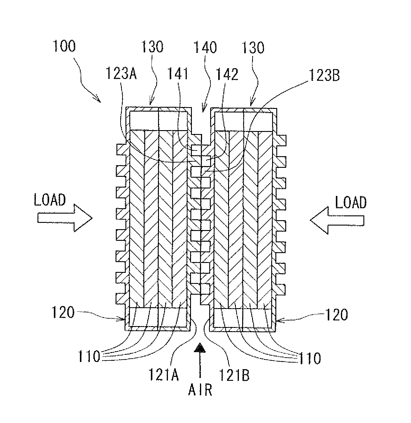
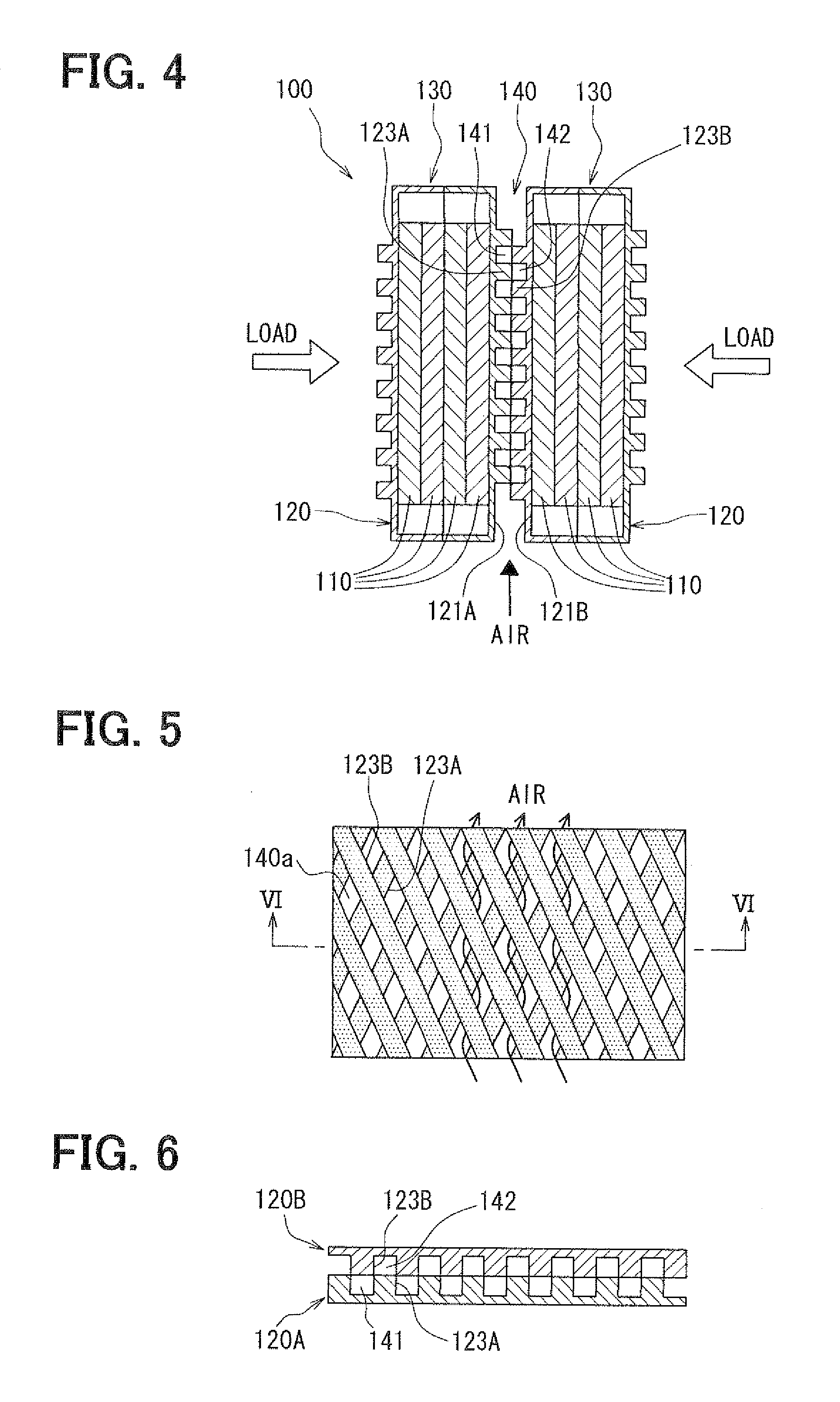
[0036]A battery pack 100 according to the present embodiment is, for example, used as a battery of a motor for running a hybrid vehicle or an electric vehicle, a storage battery for houses, and the like. Referring to FIG. 4, the battery pack 100 is constructed of a stack of battery modules 130 (e.g., at least two battery modules). Each of the battery modules 130 includes a battery case 120 and a battery cell 110 housed in the battery case 120. The battery modules 130 are electrically connected in series. A cooling passage 140 is formed between adjacent battery modules 130. Hereinafter, a direction in which the battery modules 130 are stacked, such as, a right and left direction in FIG. 4, is referred to as a stacking direction.

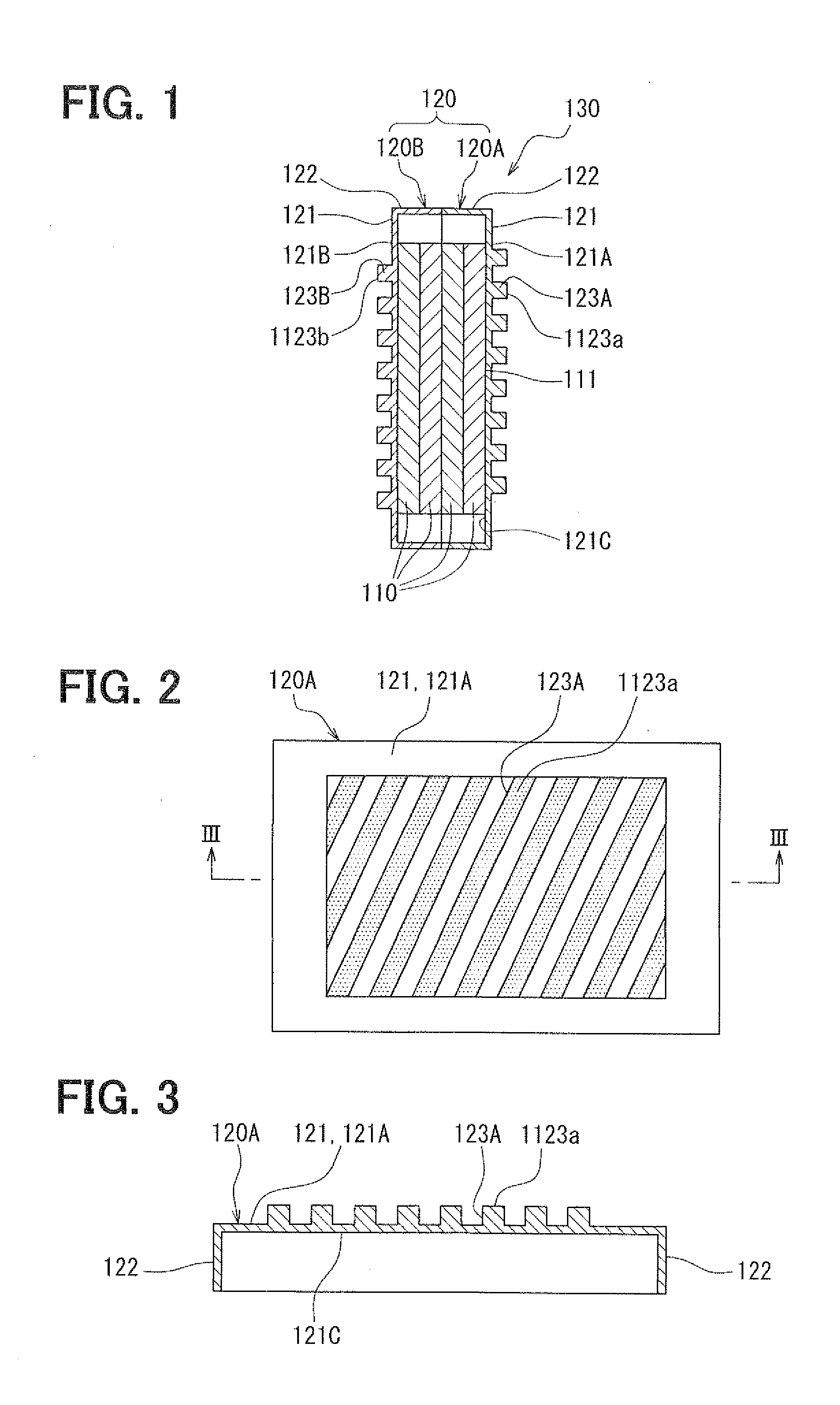
[0037]The battery cell 110 is a charge-discharge battery having a plate shape (e.g., flat plate shape) with a rectangular outline. The battery cell 110 is, for example, a nickel hyd...

second embodiment

[0077]A second embodiment will be described with reference to FIGS. 14 and 15. As shown in FIGS. 14 and 15, the first case member 120A and the second case member 120B, which have the same shape, have a male engagement portion 125 and a female engagement portion 126 for fixing in addition to the structure of the first embodiment.

[0078]The male engagement portion 125 is a projection that can engage with the female engagement portion 126. The male engagement portion 125 is located on one of four sides of the peripheral wall 122 of each of the first and second case members 120A, 120B. That is, the male engagement portion 125 is located on a first side of the rectangular peripheral wall 122. For example, two male engagement portions 125 are disposed on the first side of the peripheral wall 122. The two male engagement portions 125 are spaced from each other with respect to the longitudinal direction of the first side of the peripheral wall 122, such as, in a right and left direction in F...

third embodiment

[0083]A third embodiment will be described with reference to FIG. 16. As shown in Fig, 16, the first ribs 123A of the first case member 120A are arranged parallel to each other at an equal pitch (interval) P. Likewise, the second ribs 123B of the second case member 120B are arranged parallel to each other at the equal pitch (interval) P. The first case member 120A and the second case member 120B have the same shape, similar to the first embodiment.

[0084]In such a case, the first rib passages 141 have an equal width on the first base wall 121A. Likewise, the second rib passages 142 have an equal width on the second base wall 121B. Thus, the size of the intersectional areas 140a is equal throughout the mesh-shaped cooling passage 140. Therefore, the air can be evenly spread over the entirety of the cooling passage 140, and thus cooling efficiency of the battery cells 110 can be improved.

[0085]Since the first and second ribs 123A, 123B are arranged at the same pitch P, the contact port...


PUM


Abstract

A battery pack includes battery modules each having a battery cell and a battery case housing the battery cell therein. The battery modules are stacked in a stacking direction so that a cooling passage for allowing a cooling medium to flow is defined between opposed surfaces of adjacent battery cases. One of the opposed surfaces has first ribs projecting toward the other of the opposed surfaces and extending parallel to each other along the one. The other of the opposed surfaces has second ribs projecting toward the one of the opposed surfaces and extending parallel to each other along the other. In the cooling passage, the first ribs and the second ribs intersect each other and end portions of the first ribs and end portions of the second ribs are in contact with each other in the stacking direction.

Description

CROSS REFERENCE TO RELATED APPLICATION[0001]This application is based on Japanese Patent Application No. 2010-211094 filed on Sep. 21, 2010, the disclosure of which is incorporated herein by reference.FIELD OF THE INVENTION[0002]The present invention relates to a battery pack including multiple battery modules with battery cells, more particularly, to a battery pack with a cooling passage between battery modules.BACKGROUND OF THE INVENTION[0003]An example of a battery pack is described in Japanese Patent Application Publication No. 2009-277471. In the battery pack, multiple battery cells are stacked and electrically connected in series. A battery holder is disposed between the stacked battery cells. End plates are arranged at ends of the stack of battery cells with respect to a stacking direction. The end plates are connected by a binding band. The binding band exerts a binding force to the battery holder in a direction along the stacking direction to fix the stacked battery cells.[...

Claims


Application Information

Patent Timeline
IPC IPC(8): H01M10/50H01M2/10H01M10/60H01M10/613H01M10/617H01M10/625H01M10/647H01M10/6557H01M10/6562H01M10/6563H01M10/6566
CPCH01M10/5073H01M10/5004H01M10/6566H01M10/60H01M10/613Y02E60/10H01M6/5038H01M50/258H01M10/617
Inventor SOUKI, TAKAHIROKAMEOKA, TERUHIKOYAMADA, MANABUSHIMIZU, SHINJIROUHATA, NAOYAITAGAKI, MASAKIINOUE, YOSHIMITSU
Owner DENSO CORP
Why Eureka
Try Eureka