ECCENTRIC JET TYPE LOW NOx OXYFUEL BURNER

a burner and nox technology, applied in the direction of burners, combustion types, indirect carbon-dioxide mitigation, etc., can solve the problems of nitrogen oxide excessive generation, low flame stability and combustion efficiency, and inability to high-speed direct injection of fuel, so as to reduce the optimum mixture rate forming area, reduce the and reduce the effect of enlargement of the thin fuel area and the excessive fuel area

Inactive Publication Date: 2012-03-22
KOREA INST OF ENERGY RES
View PDF1 Cites 7 Cited by
  • Summary
  • Abstract
  • Description
  • Claims
  • Application Information

AI Technical Summary

Benefits of technology

[0015]The oxyfuel burner according to the present invention reduces an optimum mixture rate forming area in comparison with a conventional coaxial-injection, and enlarges a thin fuel area and an excessive fuel area so that partial generation of a flame with a high temperature is restricted. Therefore, an amount of generated nitrogen oxide can be minimized and the stability of a flame can be significantly improved.
[0016]Particularly, the oxyfuel burner according to the present invention combines a fuel nozzle and an oxygen combustion nozzle having different diameters so as to use them so that it is very simple and practical to design and manufacture the oxyfuel burner.
[0017]Also, the oxyfuel burner flame can achieve a flame of various shapes and a combustion characteristic according to the rotation of a fuel combustion nozzle (or an oxygen combustion nozzle), thereby flexibly functioning as a low-pollution heating control apparatus applied to a thermal process in various industries.

Problems solved by technology

Meanwhile, in a case of a low NOX oxyfuel burner performing combustion by directly injecting fuel at high speed, the high-speed direct-injection of fuel is impossible at an early stage of operation, because a temperature is low so that flame stability and combustion efficiency are low due to the structure of a nozzle.
Herein, such a flame range of a high temperature inevitably expands so that a nitrogen oxide can be excessively generated.
Therefore, in order to prevent this, the shape of a nozzle of a burner may be complicated and there is a difficulty in manufacturing and assembling.

Method used


Image

  • ECCENTRIC JET TYPE LOW NOx OXYFUEL BURNER
  • ECCENTRIC JET TYPE LOW NOx OXYFUEL BURNER
  • ECCENTRIC JET TYPE LOW NOx OXYFUEL BURNER

Examples


Embodiment Construction

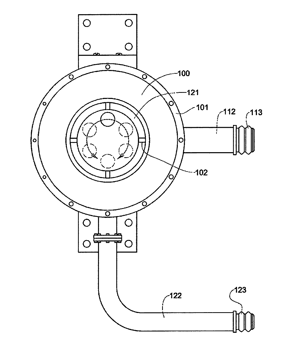
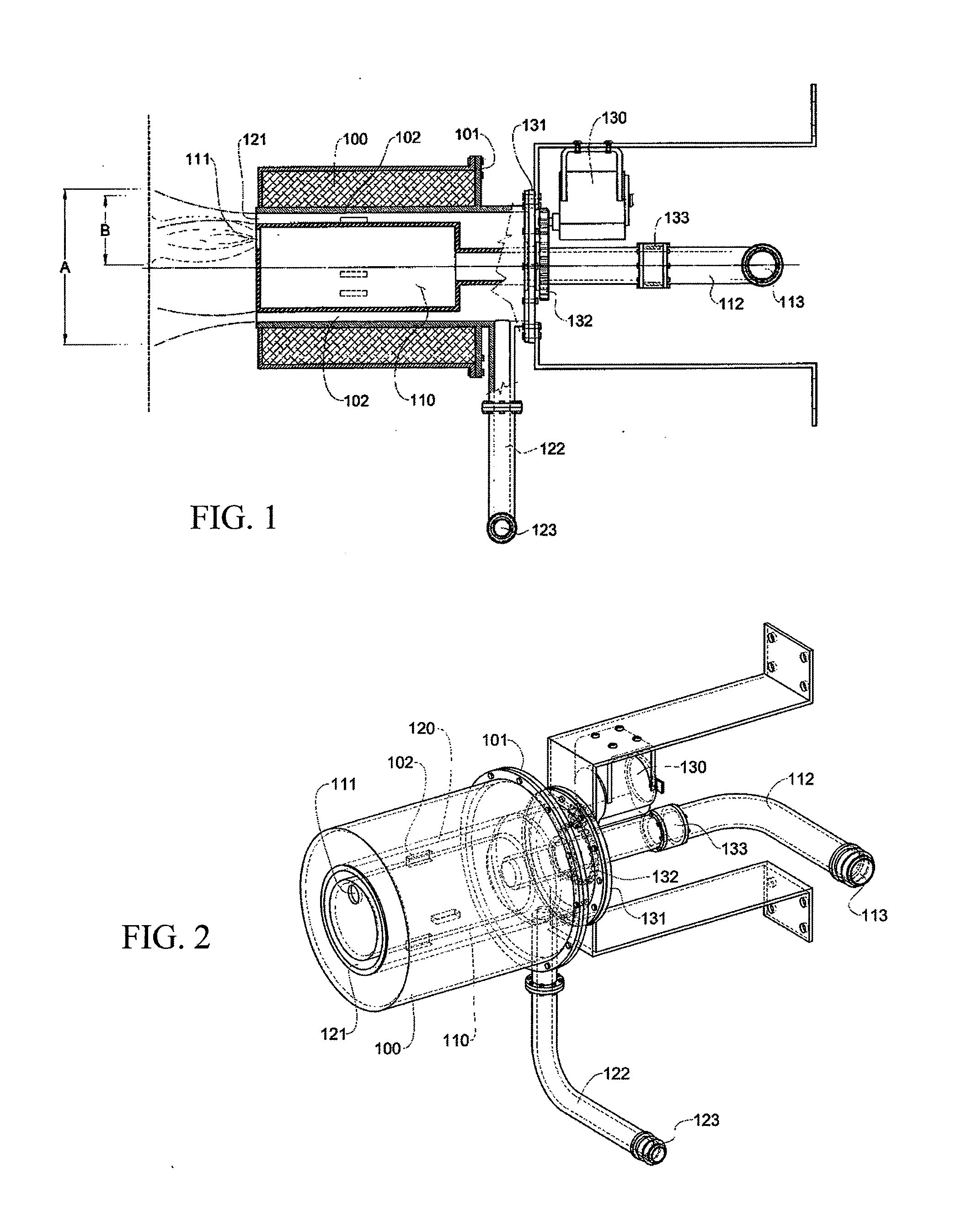
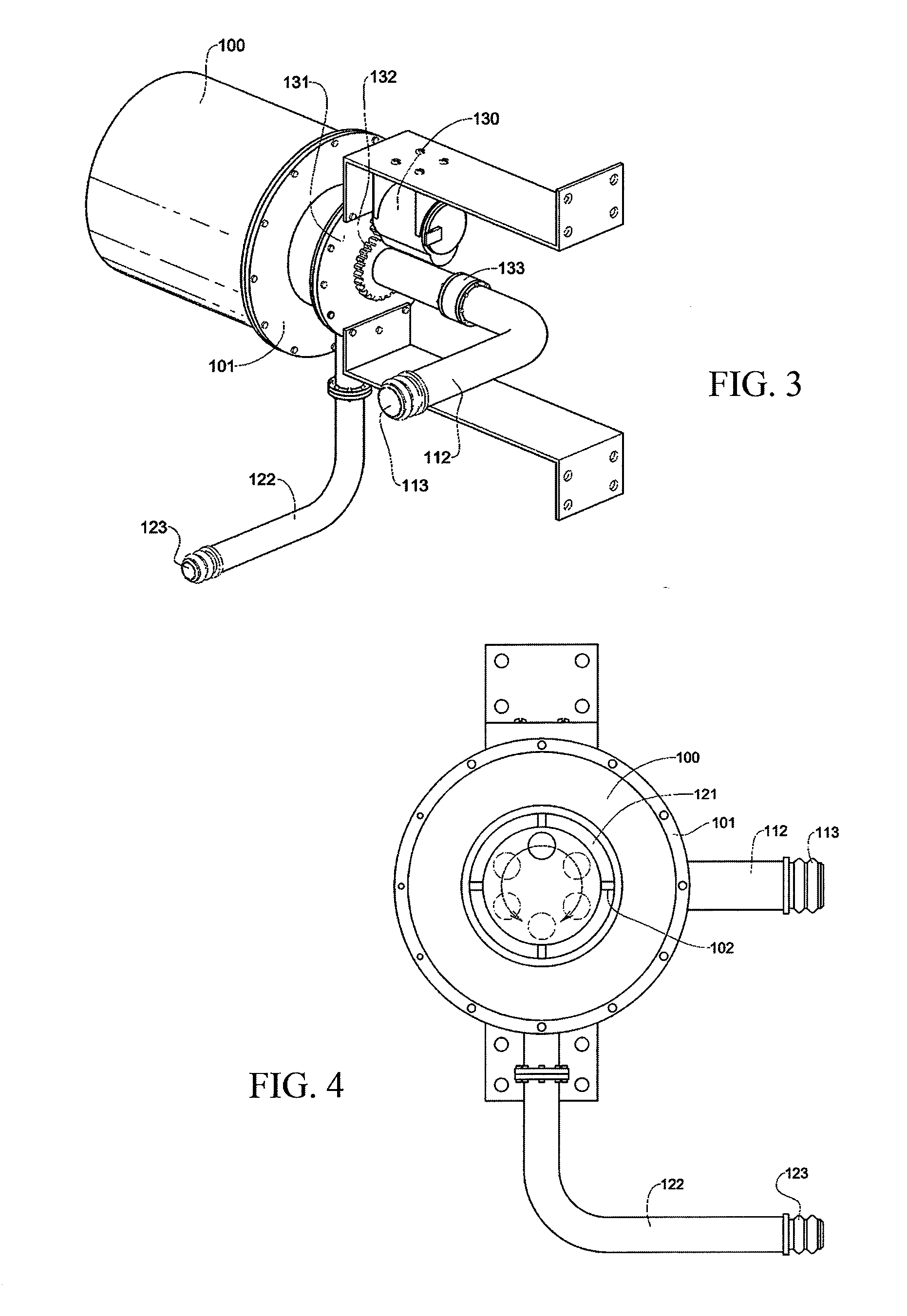
[0024]The present invention includes a fuel combustion pipe and an oxygen combustion pipe which have diameters different from each other respectively, and one combustion pipe is inserted into the other combustion pipe so that the one combustion pipe can rotate about a central axis of the other combustion pipe. Therefore, a mixture rate between oxygen and fuel can be freely controlled by an eccentrically provided nozzle of the one combustion pipe so that various combustion characteristics can be achieved.

[0025]The eccentric jet type low NOX oxyfuel burner for gaseous fuel, according to the present invention, includes an oxygen combustion pipe and a fuel combustion pipe.

[0026]The oxygen combustion pipe is inserted within a burner tile so as to be concentrically positioned with respect to the central axis of the burner tile, includes an oxygen feeding pipe connected to one side portion of the circumferential surface thereof so that oxygen is supplied through an oxygen feeding inlet pro...


PUM


Abstract

Disclosed is an eccentric jet type low NOX oxyfuel burner for gaseous fuel, which freely controls the shape of a flame and a combustion characteristic by using an eccentric injection nozzle. The disclosed oxyfuel burner reduces an optimum mixture rate forming area in comparison with a conventional coaxial-injection, and enlarges a thin fuel area and an excessive fuel area so that partial generation of a flame with a high temperature is restricted. Therefore, an amount of generated nitrogen oxide can be minimized and the stability of a flame can be significantly improved. Particularly, the oxyfuel burner combines a fuel nozzle and an oxygen combustion nozzle having different diameters so as to use them so that it is very simple and practical to design and manufacture the oxyfuel burner.

Description

BACKGROUND OF THE INVENTION[0001]1. Field of the Invention[0002]The present invention relates to a low NOX oxyfuel burner, and more particularly to a low NOX oxyfuel burner for gaseous fuel, which can freely control the shape of a flame and combustion characteristics and uses oxygen of low purity.[0003]2. Description of Related Art[0004]An oxyfuel burner applied to thermal equipment used for industrial and commercial purposes requires a high combustion efficiency, and a performance which minimizes the generation of pollutants and achieves variable and stable flame characteristics, as well as structural simplicity and endurance.[0005]A conventional low NOX oxyfuel burner performs a method for dividing and injecting oxygen or fuel in a multistage manner and has spatially various mixture rates according to each division rate.[0006]In other words, the conventional oxyfuel burner divides fuel and oxygen into fuel at low concentration and oxygen at high concentration or into oxygen at low...

Claims


Application Information

Patent Timeline
Patent Type & Authority Applications(United States)
IPC IPC(8): F23D14/22
CPCY02E20/344F23D14/32F23D14/22Y02E20/34
Inventor NOH, DONG-SOONLEE, EUN-KYUNGKO, CHANG-BOK
Owner KOREA INST OF ENERGY RES
Why Eureka
Try Eureka